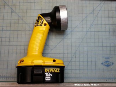
I have this Dewalt 18V incandescent "lamp" what plugs into the Dewalt batter pack
this model, in case anyone wants to buy one for a similar project. I trade it/barter for it many years ago, and it has been sitting in a shelf in my home office - just sitting there, as I hoped to eventually do something with it. I like it since with the heavy battery base, it can stand on its own, and have the head pivot at either horizontal or vertical, which might come handy.
I wanted to take it camping with my son's scout pack on March, but I ran into some trouble, and I could not finish on time. This weekend I finished it

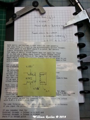
I measured the threads on the head as best as I could - something like 18TPI:
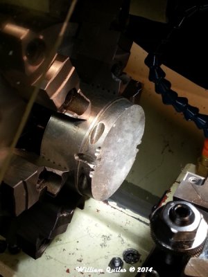
I started with a scrap piece of Aluminum - gummy, does not machine well (certainly not 6061), but it was "free", so I used it as a base for this project:
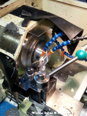
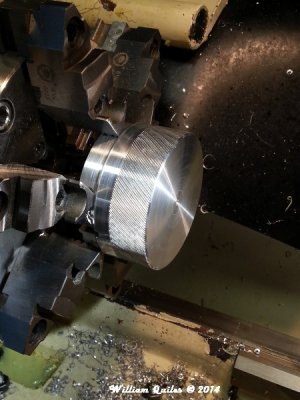
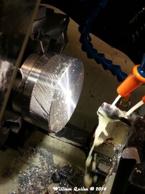
To give the new head/heatsink a non-slip surface, I gave it a swirl knurling finish:
Then face, and bore for the thread side:
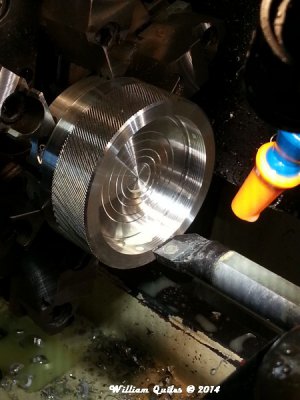
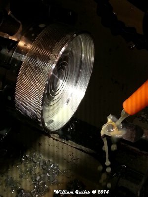
Then cut the threads, and test fit:
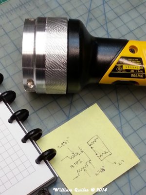
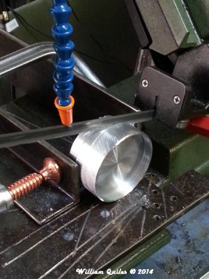
Cut the "excess" in my revamped bandsaw:
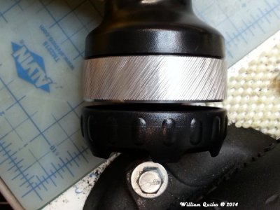
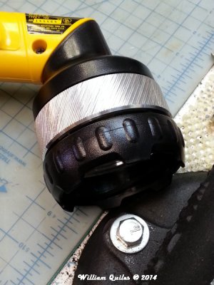
After machining the oposite side for the LED and the lens pocket, the head was finished. Here it is compared to the original plastic retainer ring:
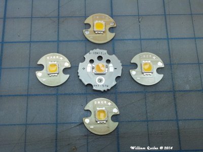
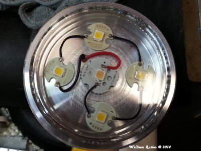
For the LED head/heatsink, I decided on color quality over quantity, so I used several LED's with a high CRI value, which I had in my storage for 3-4 years:
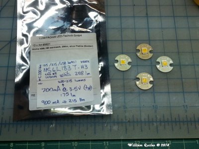
and in the middle, I used on the McGizmo high CRI LED's he sold years ago:
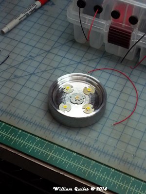
Not pretty, but this is how I decided to plug the head/headsink to the swiveling base:
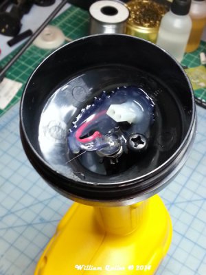
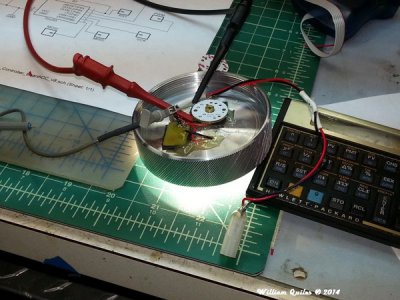
Now, since these packs charge to higher than 18V (actually in the 21V range), I decided to use one of my own PWM LED controllers, connected in direct drive (for high efficiency), and to make it adapt to the temperature in the head - so as it warms up (new/fresh batter), the PWM duty cycle gets smaller (which lowers the temperature), and once the temperature lowers, it can go back to the initial, higher duty cycle. Of course I have a 5C histeresys in the software, so that this is all very gradual, and automatic (Tiny85 gets calibrated at programming time). Of course, I can't connect a 3V PWM signal without some sort of switch, so again, I am using one of my own small MOSFET boards as the switching element. Here is the setup in my bench - I have a "sticky" thermal pad between the boards and the metal head, and epoxy to keep them in place (that schematic is the one for the "white" PWM controller board I designed):
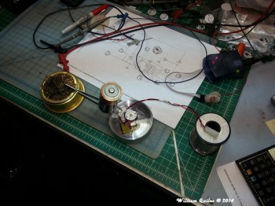
Bench testing. The back of the my controller board has the Tiny AVE programming pins, so that I can re-program/fine-tune as part of the development of the firmware settings - right now I am letting the head get to about 48-50C before picking a lower PWM duty cycle:
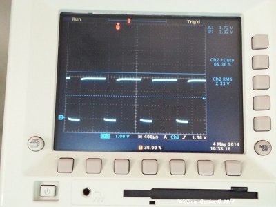
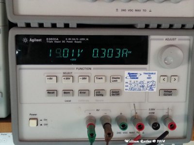
Here is the initial duty cycle setting - about about 68-69% (yes, I am under-driving everything, for cooler temps, and longer runtimes):
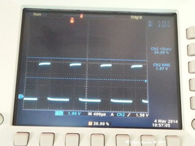
Once the temperature level is "hit" the PWM adjustment takes place, lowering the RMS current, thus starting the "cooling" process for the LED's - here the duty cycle is 50% lower than initial, at about 34%:
Finished product:
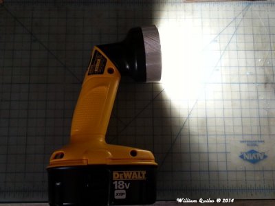
I just simply used the original plastic lens, and glued it down in place using epoxy:
Up and running (pun intended!):
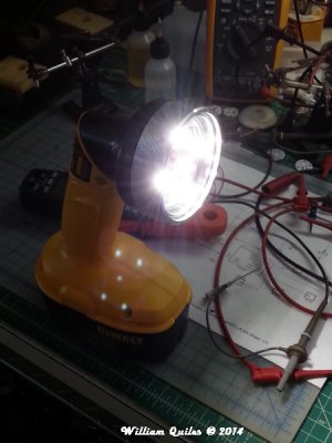
Not too bad for stuff/pieces I have laying around, right?


