New issue-Lathe Power panel config...

tjm_ar

Registered
Registered
Joined
Dec 6, 2018
Messages
20
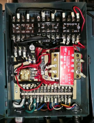
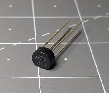
First, everything works, but I'm looking for some information. This all references the picture posted below but doesn't show the front panel and FWD-OFF-REV switch up front. The configuration is one that appears to be found on a number of Taiwanese lathes. This one is a Frejoth but I've seen one labelled as a Rutland. 'Standard' config - the two top C-16G contactors are for motor Forward and Reverse, the C-11G provides the main power and emergency shutoff. There is an overload protection device below the C-16G on the left and the transformer has a 240VAC input (configurable) and a 24VAC and 110VAC output. The 110VAC output is not used. The 24VAC system passes current through the 5A fuse and operates the contactors and the small, clear plastic encased relay below the overload unit. That relay is the main issue. That small relay is a 24VDC relay and wired with a bridge rectifier (also pictured) with specs that match this picture and operates that relay coil. This small relay is the 24 volt subsystem that powers the front panel and Forward-Reverse switch to operate the contactors.

Here is the big question: Is there some advantage to operating this relay with 24 volts DC as opposed to not having the rectifier and using a normal 24 volt AC relay?
My first thought is there was a box of DC relays laying around and a $.50 rectifier made them usable as opposed to a $7 AC relay. What am I overlooking? I have both AC and DC replacement relays and I need to change the damaged relay socket anyway, so can I get rid of the extra rectifier wiring or leave it alone?

Thanks,
tjm
 

Attachments

  • FrejothPanel.png
    FrejothPanel.png
    1.4 MB · Views: 21
  • Rectifier_c.jpg
    Rectifier_c.jpg
    281.6 KB · Views: 9
Last edited:
I believe DC relay systems are more efficient, with less hum and less heat. Many industrial 24 volt control setups use DC relays.
Answer your question?
-Mark
 
I believe DC relay systems are more efficient, with less hum and less heat. Many industrial 24 volt control setups use DC relays.
Answer your question?
-Mark
So that's what I need to do to get rid of the 'hum' on my 1440?
Add that to my 'To-Do' list, after I learn how to do it...
 
I believe DC relay systems are more efficient, with less hum and less heat. Many industrial 24 volt control setups use DC relays.
Answer your question?
-Mark

Mark, it does partially answer the question. But why only the small relay then keep the contactors on 24VAC?
 
Leave the 24VDC relay and bridge rectifier as is, at 24VAC the relay could chatter with the AC wave and may break the latch which holds it closed. This arrangement is used on just about every small lathe that I have seen. The contactors on smaller machines operate on 24VAC, the coil characteristics I assume are different that contacts do not chatter with the fluctuating AC. I had an experience with using a 110VAC contactor systems and using the contactors to operate VFD inputs and the results were not predictable.
 
Leave the 24VDC relay and bridge rectifier as is, at 24VAC the relay could chatter with the AC wave and may break the latch which holds it closed. This arrangement is used on just about every small lathe that I have seen. The contactors on smaller machines operate on 24VAC, the coil characteristics I assume are different that contacts do not chatter with the fluctuating AC. I had an experience with using a 110VAC contactor systems and using the contactors to operate VFD inputs and the results were not predictable.

Got it, thanks. For a change on my part, it works so I'm gonna leave it alone.
 
Middleroad: Yes, if your contactors are humming like a beehive, convert to a dc contactor system. If I'm not mistaken, you can run your ac contactors on dc, so you just need to add a bridge rectifier to the system and maybe a small smoothing cap. Maybe someone can chime in on this?
-Mark
It's possible there may be residual magnetism problems with using ac contactors on dc, can't say for sure
 
You cannot add a rectifier and power an AC coil with DC at the same voltage; that will burn up the coil. If you want to change a relay/contactor with an AC coil to DC, it will be necessary to change the coil (in some cases you would have to replace the relay or contactor).
 
One point of concern with both relays and contactors is that when released and the relay springs open they can generate a significant voltage spike which could damage other devices such as solid state equipment and also any controllers/VFD control inputs that are on the same line. The spikes are not trivial, a 24VDC relay can generate a reverse DC voltage spike way over 100V. So it is common to use a reverse diode (may be with a zener/resistor) on the DC relays/contactors and a RC snubber circuit on a AC relays/contactors to slow the rate of change. Relay sockets will often have a plug in socket for the suppressor module, contactors they plug into the top. The problem is less of an issue if you only have a transformer that can absorb the spike, but if you used the same power supply for other equipment it could be damaged. I also have used capacitors across the inputs of DC relays to delay their release time when I needed to stagger the timing between relays.
 
often times, suppressors are used on dc coils, and i have seen resisted leds to take the spike

24VAC coils operate just fine in many industrial situations, but i prefer 110VAC control systems

AC control systems are way more reliable than DC systems
 
Back
Top