PM25-MV saddle squareness

The base is sheet metal and not precision. It has to be shimmed. I bet if you set it down on a surface plate it would be fine. If PM was smart they would have 3 legs ( 3 main points) and on the corner have smaller jacks and hold downs on the 4 corners. Yo eliminate twists.
 
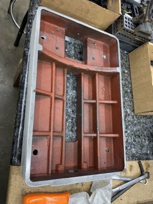
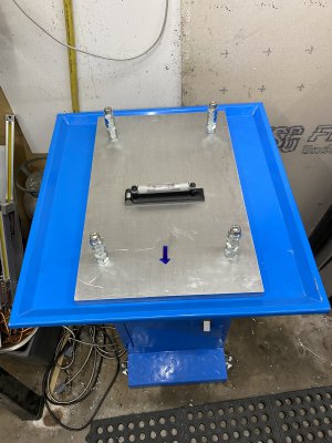
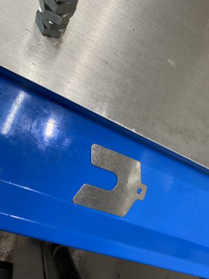
I spent the last 3-4 hours playing around with the mounting bolts, tightening/loosening them individually, and re-checking squareness in between. I made a mental image of how the base of my mill was twisted and ended up shimming between the base and my stand to reverse the twist. I added a .038" shim to the rear right corner and am now seeing less than .0005" out of square in Y. I'm at the point where I can't do any better without purchasing some higher precision tools due to the error stack up (vise trammed within .0003" and my 123 block being out of square approx. .0002"). Either way, I think I'm going to call it good for now - it's a major improvement over the .008" I was seeing originally. I machined a 2"x3" block and checked it with a square comparator on my surface plate. It showed approx. 4-5 tenths out of square over 3 inches.

I just want to iterate how accomodating Matt and the customer service at Precision Matthews has been. When I originally emailed Matt I explained that I knew the mill was well out of warranty due to the CNC conversion and if it came down to it, I was OK purchasing a new saddle from him. He assured me that if the saddle was truly machined out of square, he would replace it under warranty because he recognized that the conversion had nothing to do with it. Overall, Precision Matthews has been a great company to deal with.


Let us know how the grinding turns out.
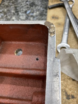
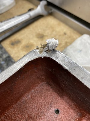
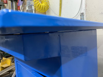
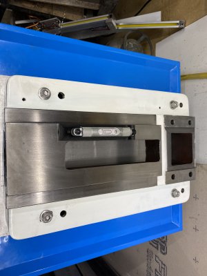
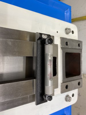
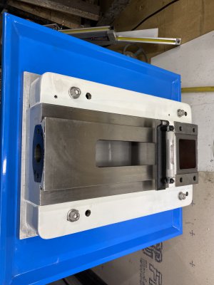
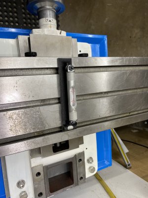
Grinding was done today and the mill is back together. The saddle is now less than 0.0002" flat:). Unfortunately the issue remains with the saddle twisting/flexing when the table is not centered to the Y axis. When the table is centered the mill indicates in perfectly, but when moving 3 inches either direction from center I find the saddle twists and I get a gap like before. Move the table to the left and get a 0.003" gap in the front right corner. Move to the right and get a gap in the left rear corner. Like tkalxx did, I too spent 3-4 hour trying to level the base with shims. I am now temped to take the mill apart down to the base casting and have it ground as well. Not sure what to do after that.
 
I still think part of the issue is the stand. Your bolting it down to a not precision stand. Or the saddle top to bottom is not co-planer, If the indicator changes when you reverse the travel that probably means the center of the positive side of the saddle Y is high in the middle. I wish I lived closer I am sure I could figure it out and fix it for you. I do have some students who live near Sacramento who get together now and then. I bet if your took it to one of there weekend get- togethers and they could figure it out. They all can scrape too. Did you take some photo's when you had it ground? You may want to ask or cut and paste this into the Rebuilding forum and most of my friends in CA are members of Hobby Machinist and read the rebuilding forum. I'll ask them to come here and help. Rich

Link to the rebuilding forum:

 
Last edited:
Happy to help if I can, and I'm sure the rest of the folks from our group would be as well. We are hardly (read, "NOT") expert rebuilders but Rich has taught many of us a few things, so there is always hope (laugh).

Of course you're in Sonora! I'm down in the San Jose area, and most of the other folks are up toward Sacramento. Almost a perfect triangle: you're about 100 miles from either. PM me ("start a conversation" on this forum) if you'd like to figure out a way to get together.
 
The group has not had a monthly meeting since the pandemic came upon us, and so far none have been planned.
 
I still think part of the issue is the stand. Your bolting it down to a not precision stand. Or the saddle top to bottom is not co-planer, If the indicator changes when you reverse the travel that probably means the center of the positive side of the saddle Y is high in the middle. I wish I lived closer I am sure I could figure it out and fix it for you. I do have some students who live near Sacramento who get together now and then. I bet if your took it to one of there weekend get- togethers and they could figure it out. They all can scrape too. Did you take some photo's when you had it ground? You may want to ask or cut and paste this into the Rebuilding forum and most of my friends in CA are members of Hobby Machinist and read the rebuilding forum. I'll ask them to come here and help. Rich

Link to the rebuilding forum:

You are correct. I disassembled the entire mill today for one last check of everything. I found the stand is not helping and either was this glob of paint from the factory. I scraped everything clean and hit it with a stone for sharp edges. It still rocks a little, but before I put it back together I will be adding a 12"x18" by 1"thick plate to the mount the mill base to and will shim the under side of that plate to the stand. While I had it apart I did add 1/2-20 threads to the corners of the mill casting base for leveling if needed. Thanks for the offer to have the club look at it. I think I have it under control at this time.
 

Attachments

  • AQHW6399.JPG
    AQHW6399.JPG
    2.5 MB · Views: 135
  • SAFP5787.JPG
    SAFP5787.JPG
    1.6 MB · Views: 126
  • XTYK9053.JPG
    XTYK9053.JPG
    1.7 MB · Views: 130
Happy to help if I can, and I'm sure the rest of the folks from our group would be as well. We are hardly (read, "NOT") expert rebuilders but Rich has taught many of us a few things, so there is always hope (laugh).

Of course you're in Sonora! I'm down in the San Jose area, and most of the other folks are up toward Sacramento. Almost a perfect triangle: you're about 100 miles from either. PM me ("start a conversation" on this forum) if you'd like to figure out a way to get together.
Every day that I work on this I find one more little item that adds to the twisting issue. Today it was a build up of old paint under the base. Now that I have everything clean and not constrained I have a better understanding of what is causing the twist. Thanks for the offer to help, if I can't get it right afet this next go around I will let you know.
 
I see you have a surface plate. Flip the base over on it and see if it sits on it flat. Take a soft blow hammer and tap around the perimeter and listen for a solid thud where it touches. Then listen for a clapping and hollow sound and when you find it slide on feeler gages. It may take overnight or a few days for it to twist straight if it was ever right. Once you get it solid all around the perimeter take a height gage and a dial indicator to see if the top of the base ways are all on the same plane or co-planer. Then set the saddle on the base and indicate the top of the saddle and see if it is co-planer to the base ways. It's like building a house. You have to have a solid foundation and built square and co-planer all the way up. If not you get the multiplication of errors and it will never be correct. Grinding a crooked part on a grinder is not the answer, unless you shim the twisted part before you turn on the magnet. If not you mag it down and it is cockeyed, then release the magnet it goes back cockeyed. I always scrape the cockeyed base first so it sets on the magnet or surface plate first.
 
Mill update. The mill base is now level and is as flat as possible. I Put a .75' thick aluminum plate between the mill base casting and the chip tray/stand. I first set the mill base casting upside down with the dovetail face on my surface plate and set the aluminum plate on top of casting, basically letting the aluminum sit in a free state on the casting. I then checked for gaps between the aluminum pate and the casting. I was relieved that there were no gaps more that .001". I put the chip tray on the stand with the aluminum plate. With the plate loose I leveled the stand this allowed me to pick the appropriate shim needed to fill the gaps between the stand and chip tray. With the shims in I started to tighten the bolts that hold the casting down, anytime the level moved I added or removed shims. If you noticed I didn't have short enough bolts so I used nuts as spacers. As I put the mill back together I kept checking it for level as I went. As seen by the pics it stayed fairly level in X and Y during assembly.

The squareness has improved and the gaps between the saddle and dovetails are gone. There is little if any flex when the X table travel end to end, but I still have a slight squareness issue. Seems the mill still is out .003" over 4" in the X or Y axis. I doesn't matter which axis you indicate in the other axis is always 0.003" out. I still believe the issue is in the saddle. The CMM report did show it out of square 0.004"

Shims used.
0.065" Right Rear
0.005" Left Rear
0.020" Right Front
0.040" Left Front
 

Attachments

  • IMG_0309.JPG
    IMG_0309.JPG
    1.9 MB · Views: 105
  • IMG_0311.JPG
    IMG_0311.JPG
    2 MB · Views: 102
  • IMG_0312.JPG
    IMG_0312.JPG
    3 MB · Views: 108
  • IMG_0313.JPG
    IMG_0313.JPG
    1.8 MB · Views: 103
  • IMG_0314.JPG
    IMG_0314.JPG
    1.6 MB · Views: 96
  • IMG_0315.JPG
    IMG_0315.JPG
    1.6 MB · Views: 107
  • IMG_0316.JPG
    IMG_0316.JPG
    1.7 MB · Views: 93
  • IMG_0317.JPG
    IMG_0317.JPG
    1.5 MB · Views: 105
  • IMG_0318.JPG
    IMG_0318.JPG
    2 MB · Views: 101
  • IMG_0319.JPG
    IMG_0319.JPG
    2.4 MB · Views: 99
That level graduations are .005" per line? You may want to eyeball the bubble on the exact line to get it closer. If that is acceptable for you, then use it. If not arrange for one of the club members to come help. Many of them are retired. John York has all the tools needed as does Rex. They could scrape it square. The set up you have looks nice.
 
Back
Top