Pm727v spindle control board

Cad cam man

Registered
Registered
Joined
Mar 5, 2021
Messages
55
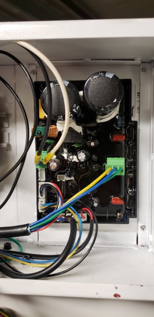
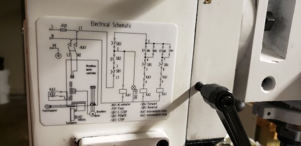
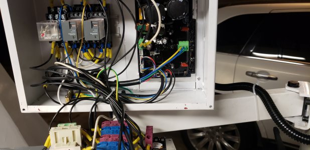
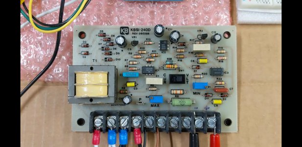
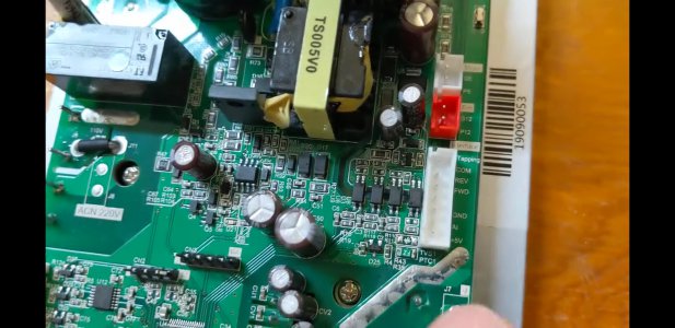
Hey guys I got my pm727v about 3 weeks ago and I am in the process of converting it to cnc . I am at the point now where I need to get control of the spindle using centroid acorn so when I open the control panel where the on/off spindle forward/reverse is the board that has the wiring for the 0-10v and the pot wires is all covered in black security plastic. I have attached pictures but my question is does any one have a picture of the board without all the black coating on it ? Is this just mine or did every pm 727v have this ???? I have a basic schematic label on the side of the mill ofcourse its not enough information to wire what I need. I am trying to wire the kbsi 240d with centroid acorn to gain spindle control any help is greatly appreciated
 

Attachments

  • 16175001724586036194915498678952.jpg
    16175001724586036194915498678952.jpg
    948.2 KB · Views: 151
  • 16175002561673405371887107787914.jpg
    16175002561673405371887107787914.jpg
    1.9 MB · Views: 148
  • 16175002804311422540309215143045.jpg
    16175002804311422540309215143045.jpg
    2.3 MB · Views: 167
So the potentiometer comes in on the small connector in the corner of the board with three wires black, yellow and blue. The black is probably ground (0 volts), the blue is likely +5 or some other positive voltage, and the yellow is the pot wiper. The colors could be different- check the pot itself.
Are you aware of the need for line isolation for one or both devices? You don't want to blow up your boards. I would wager the PM is NOT isolated.
If the Acorn is you may be OK. This is very important, you need to be sure before connecting anything. Have others done this connection successfully or are you blazing a trail here?
How much electronics experience do you have? I need to ask because we are talking about possible shock hazard situations. We haven't had any members get electrocuted or burn down their house (yet) and we don't want you to be the first
-Mark
 
Last edited:
I'm just a newbie here, and I hate to disagree with Mark, but looking at the pictures, the yellow and blue wires appear to go to relays (KA2 and KA3). I think the black, brown, and (darker) blue wires to the lower right of those are probably the potentiometer wires, but I'd trace the wires to be sure....

-Pete
 
Yes my mistake, it's hard to see
In any case, need to be sure the controller board common isn't hot with 120 volts AC and if it is, you'll need an isolation transformer
 
Last edited:
So the potentiometer comes in on the small connector in the corner of the board with three wires black, yellow and blue. The black is probably ground (0 volts), the blue is likely +5 or some other positive voltage, and the yellow is the pot wiper. The colors could be different- check the pot itself.
Are you aware of the need for line isolation for one or both devices? You don't want to blow up your boards. I would wager the PM is NOT isolated.
If the Acorn is you may be OK. This is very important, you need to be sure before connecting anything. Have others done this connection successfully or are you blazing a trail here?
How much electronics experience do you have? I need to ask because we are talking about possible shock hazard situations. We haven't had any members get electrocuted or burn down their house (yet) and we don't want you to be the first
-Mark
Just want to start off by saying yes there is another fellow that has done this connection and he was going off of what another guy showed him so there are a few people that have done this . If you look up Franco cnc on YouTube you will find the conversion he is starting with his pm728vt. I will be following the same wiring as he did . Back to the reason of the post I need a picture or schematic drawing of the control board do either of you guys have this ??
Yes my mistake, it's hard to see
In any case, need to be sure the controller board common isn't hot with 120 volts AC and if it is, you'll need an isolation transform
 
You do have a picture ? Or schematic ? Can you post a picture of the board
 
Sorry, no I don't have the schematic of the PM727 controller. I wonder though why you would need it? Are you not simply providing a control voltage in place of the speed pot on the PM controller? Seems pretty straightforward if the line isolation is not an issue
-Mark
 
Lol no that's not all..... along with the control voltage I need gain control over the forward and reverse. I need to see of this board has the tapping function as seen on the pm728vt. Having the schematics or a picture of the silk screen writing would help big time. Since I do not have this I will have to chase all the wires and I was trying to avoid this. I have attached the signal isolation board (kbsi240d) and a picture of the pm728vt board for example of what I need from the pm727v. There are a few other components I have left out like the Acorn board and the encoder I will be adding and the relay board
 

Attachments

  • Screenshot_20210404-142621_YouTube.jpg
    Screenshot_20210404-142621_YouTube.jpg
    1.1 MB · Views: 131
  • Screenshot_20210404-143140_YouTube.jpg
    Screenshot_20210404-143140_YouTube.jpg
    1 MB · Views: 119
Ah I suspected that's what you were after. Well if all the wires are there it shouldn't be too much work to trace out. It's unfortunate that they potted the board with epoxy. I have found glacial acetic acid will dissolve that but it's horrible stuff to work with. Fumes like you wouldn't believe
-M
Have you tried asking PM if they can get you a schematic?
 
Yeah thats what I was afraid of ... looks like I'm getting my tracing hat on lol . Its really not a big task but when you add up all the other rat killing it makes it 1 more thing to do . That and besides I'm a blueprint kind of guy it makes me feel a bit more comfortable when dealing with this kind of stuff
 
Back
Top