2019 POTD Thread Archive

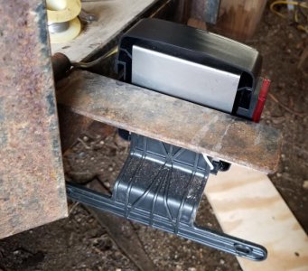
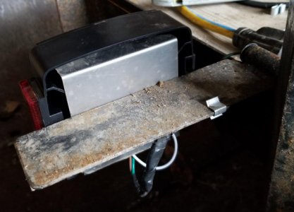
POTD was replacing the tail lamps on our 6'x10' utility trailer with LED lamps. I liked the lifespan of the LED's, but questioned the open area in the lamp where the wiring passes in the housing. I caulked it up, but naturally the tail lamps take a lot of road spray. So went the overkill route of making a couple of stainless steel shields to protect the wiring.

Cut the stainless to size on my Tennsmith shear, punched holes with a Roper Whitney #5 Junior hand punch and bent a flange on the top with the DiAcro brake. Soldered, taped and heat-shrink tubed the wiring connections. No more burned out bulbs to replace.

Bruce

New LED tail lamp. Wiring isn't well protected where it runs into the housing.
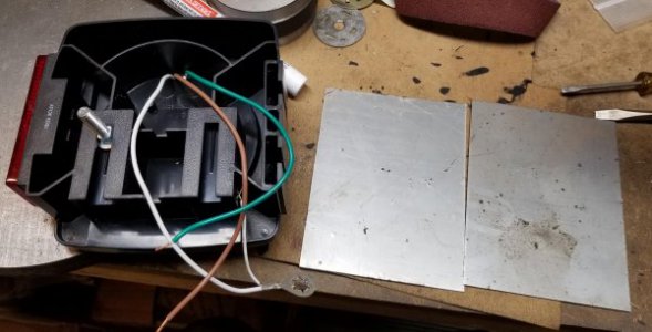
289990

Cut a pair of SS blanks on the shear, punched mounting holes.
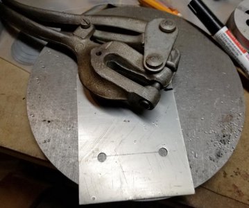
289991

Bent a flange that goes over the top inner of the housing. Left it at an obtuse angle
so it'll shed water away from the wiring though air while driving would take the water
over the top anyhow.
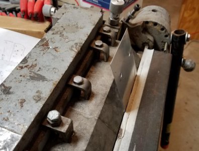
289992

Set the shields in place and filled the cavity at the top with silicone caulk.
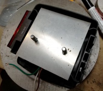
289993

New lamps in place.
289994289995
 
POTD was replacing the rubber tires on my 12" Craftsman wood band saw. I bought the saw around 35 years ago and had been milking the stretched out tires by Gorilla gluing them to the aluminum wheels. Time for a proper repair . . .

Bought a pair of urethane tires from www.polybelt.com for around $30 delivered. Installation is pretty easy though I'm glad it's not how I make my living. The instructions recommend heating the tires to 120 F to make them more stretchy. Good call, especially when my shop was a balmy 25 F at the time.

Pulled the wheels, clamped them to a bench and pulled really hard to stretch the new tires in place. The new tires should last through my lifetime.
Bruce


Didn't pull them at opposite ends for the photo to show how much the
original rubber tires had stretched, but they were about 1 1/2" longer than
the urethane replacements.
View attachment 289986

Clamped the bottom wheel to the workbench with the tire staged in place.
The kit includes a screwdriver to work the tire over the wheel, but I just went
with brute force and stretched the tire in place with my finger tips.
View attachment 289987

Top wheel wasn't coming off the upper axle, so pulled the whole mounting
assembly.
View attachment 289988

New tires in place. Runs nice and smooth, should have done this years ago.
View attachment 289989

I love them, I even replaced the tires on 2 of my bandsaws that did not quite need them. Nice not to have to worry about them. I did not take the wheels off, just mounted the tires where they were. Then run the tool around the wheel (Between the tire, and wheel), a few times to be sure the tires are evenly stretched. Its surprising how tight they fit, and hold up.
 
Bruce- good job on the saw. That's exactly the model I have (used to be my Dad's) in my shop. I've recently added a reducing gear box and converted it to metal-cutting. I'll keep that tire source in mind. Thanks for the great post.
 
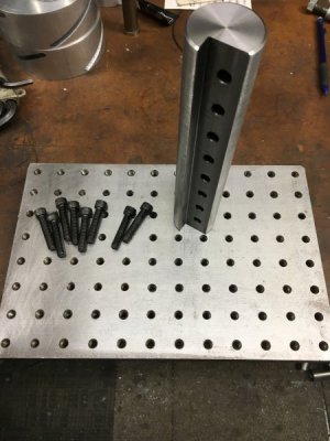
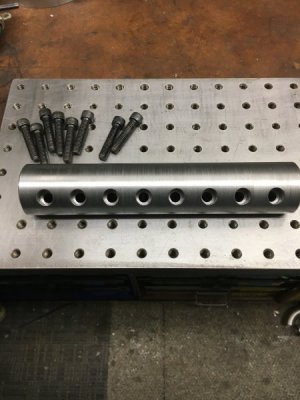
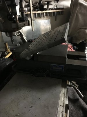
Had alittle time in the shop yesterday. Wanted to make a fixture plate I have alittle more versatile. Easy job took a piece of scrap 1 3/4 turned down to clean up. Milled a slot in top and drilled and countersunk some holes to be able to bolt up to the plate. I don't know if necessary but I'm thinking up some support arms that will bolt to the back of the movable jaw in those 1/2 holes and give the plate support on both sides through the full range of motion. Plate is 8x12 with 5/16-18 holes and can be mounted on either length of plate.
290110290111290112
 
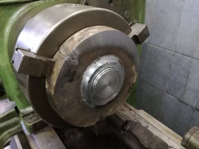
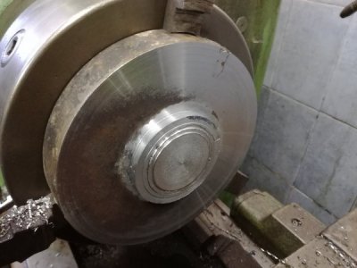
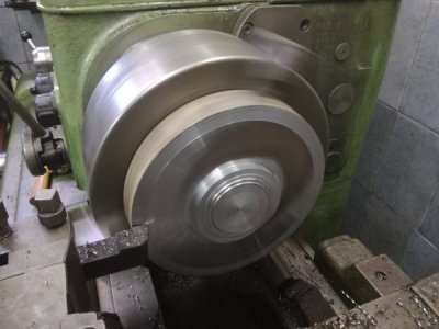
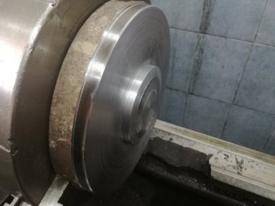
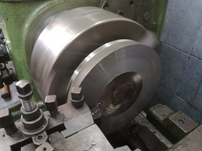
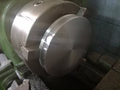
Today i decided to start work on a wheel spacer for the Little Niva, i'm still looking to buy couple more pieces of the same material to make 3 more spacers, but i want to see how it looks and to check for clearance issues, this is a plasma cut piece of 4140 or C45 steel that i had a piece welded on to make up the hub centric part, also there was a cut at the edge that i also got welded up. I started by setting it up as close to straight as possible and began cutting back the welds, then i took a small clean up cut on the face, that give me my first measurement to be sure that i can finish it at 30 mm thick, then i cut down the centre hub aria to size and began cutting the radius on it to imitate the factory hub, and cut one side of the out side part so i can chuck it up from the other side, then i flip it, secured and dial in exactly how much i need to cut off to bring it to 30 mm thick, and come exactly to size, this part needs a bit more work but i run out of time today, but i plan to continue tomorrow.
290126290127290128290129290130290125
 
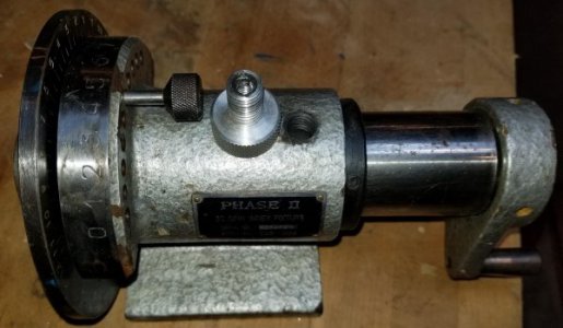
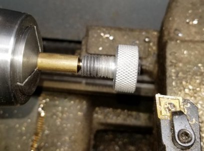
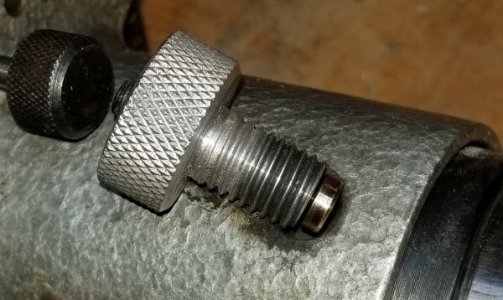
POTD was another shop tool repair. I have a Phase II spin indexer and noticed that the spindle clamp screw was missing a (presumably) brass button. The screw clamp is aluminum, so wouldn't hurt the steel sleeve, but seems like there should be a plug in the end.

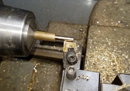
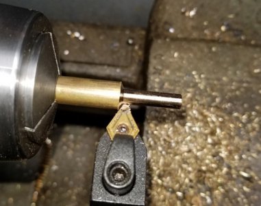
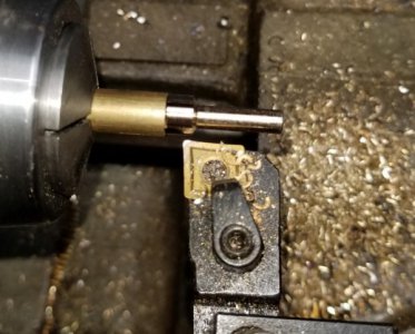
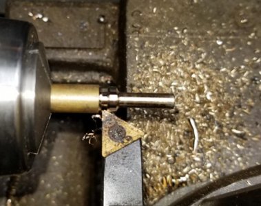
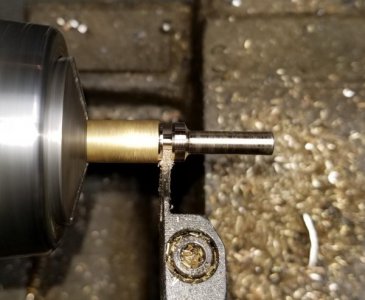
Simple lathe job: chuck up some 3/8" brass, turn a shoulder to tightly fit in the clamp screw. Made it a little long for facing to length after the fact. Then chamfered the end of the shoulder to fit into the countersunk end of the clamp screw. Cut a groove so the clamping end could be chamfered, then parted. Cleaned up the end on my Dayton 2" x 42" sander. I didn't Loctite the plug in the clamp screw as the end of the screw has a set screw which bears on the end of the brass insert. I'm guessing in use you'd turn the knurled clamp screw tight and if you wanted a little extra clamping pressure, turn the set screw to push down on the brass (though probably unnecessary).

Bruce

Phase II spin indexer clamp screw missing a soft insert on the end
290131

Turned a shoulder so the pin would fit in the screw
290132

Chamfered the shoulder so it'd set in the countersunk end of the screw
290133

Verifying fit. Shoulder was purposely turned a little long, would be faced later.
290134

Turned the sides of the plug to size so it's smaller than the root diameter of the spin indexer's threads
290135

Started parting off, then switched to a turning tool to chamfer the clamping end.
290136

Parted and cleaned up the end with a belt sander.
290137

Finished brass button in place
290138
 
Last edited:
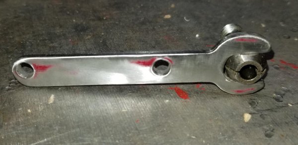
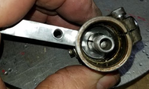
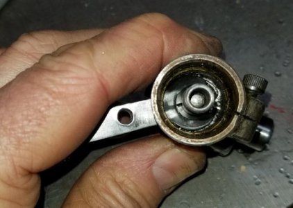
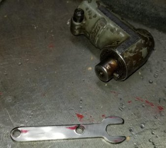
POTD was another shop tool repair/fix. I bought a Quillmaster for my Bridgeport months ago and recently picked up a QRA (Quillmaster right angle ?) attachment. The QRA is a right angle attachment for the working end of the Quillmaster and attaches to the later by tightening the QM collet on the QRA's input shaft. The collet is accessed through a slot cut in the body of the QRA. Unfortunately, the QRA I bought didn't come with the wrench, so POTD was making a replacement. Easy job for my CNC Bridgeport.

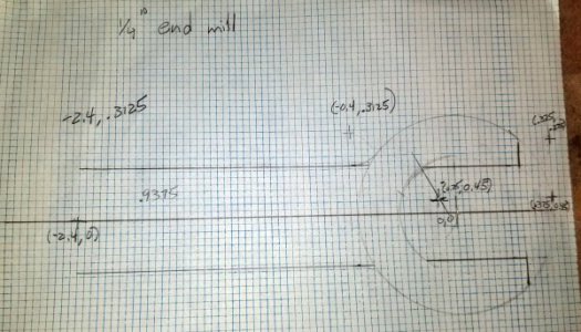
I measured the ID of the QRA at 0.75" and the flats across the QM's collet at ~0.340", collet OD is ~0.425". Used my high-tech CAD program to draw the wrench. Yeah, a sheet of graph paper with a sketch scaled up 5X. The wrench profile is a little different than normal; I made the OD of the wrench round so it'd fit neatly in the QRA's body. Drew the diameter at 0.700" for 0.025" clearance on the sides. Then drew a 0.425" diameter circle on the same center. This is the diameter of the collet, so the wrench would be centered on the collet and QRA. Then drew lines for the 0.340" slot in the wrench for holding to the flats. Figured an approx. 2" handle would be fine, so sketched that in too. Used a circle template to simulate the 1/4" end mill I'd be using to cut the wrench. Found the tangent points for the CNC moves on the Bridgeport and wrote a 30 step routine to do the job.

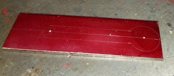
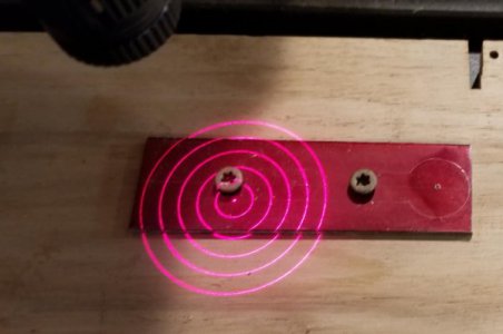
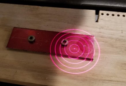
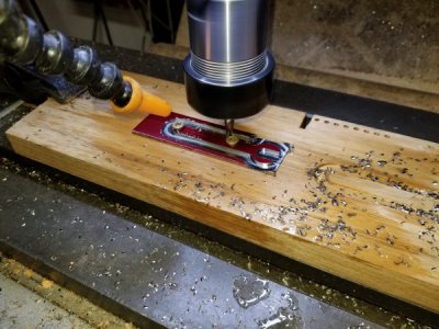
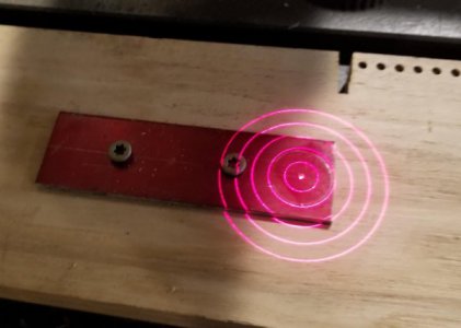
The slot in the QRA is about 0.190" tall, so some 0.100" stainless in my stock pile would work perfectly. Scribed the rough outline on the stainless and drilled a couple of holes for screwing the wrench to a sacrificial hickory board. The board was clamped to the Bridgeport's table and the scribed blank trammed in with a laser center finder. After tramming, found my (0,0) coordinate with the laser center finder.

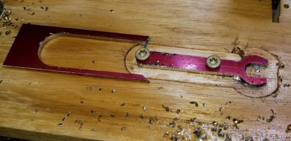
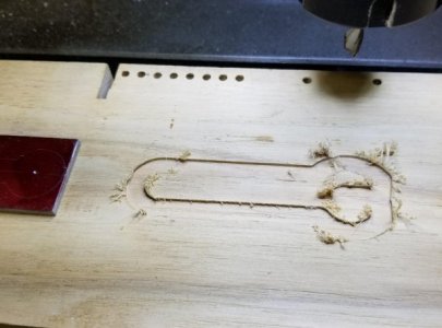
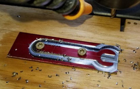
I ran the CNC routine in air for starters, then on the hickory board. Looked good, so moved to the stainless. The routine took about 45 seconds to make a loop around the wrench. Took three passes to get through the 0.100" stainless.

Dry fit the wrench to the collet, was a little snug so shaved the insides with my die filer. Cleaned up the outsides a bit with the 2" x 42" sander and a Scotch-brite wheel. Should work great.

Thanks for looking,

Bruce


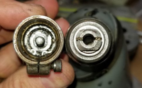
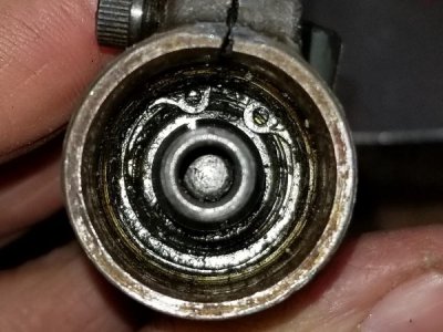
QRA Quillmaster attachment gets power through the QM's collet which is clamped to the QRA's input shaft.
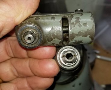
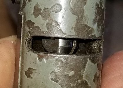
The collet is buried in the QRA housing, but is accessible through a slot in the QRA's body.
290144290145

Removed the QMs collet and slid in on the QRA's input shaft. Flats on the collet are visible through the slot in the QRA's body.
290146290147

My high-tech CAD drawing . . .
290148

Dykem'd the stainless and scribed the rough outline.
290149

Trammed in the stainless steel blank with a laser center finder, then found (0,0) with the finder.
290150290151
290152

Ran the CNC routine off to the side on the sacrificial board, then on the real deal.
290153
290154
290156

Wrench was a tight fit to the collet, so did a little filing for a looser fit.
Wrench in use with a QM's collet set on the QRA's input shaft. Works through the (limited) full range of travel.
290157
290158290159

Finished wrench and the QRA.
290160

20190310_115629.jpg
 
Last edited:
Please tell us some more about your laser center finder. Looks slick! Is it the kind that sends out a dot, and makes a circle as the quill spins ... or does it generate the circles without rotation.
 
Hi John,

I have two versions from SDA:. Cross hair with center dot and the concentric circle one used here. It projects the circles you see in the photos, spindle is stationary. Naturally, moving the quill up and down changes the diameters which makes getting on center to a boss or existing hole a snap. I can repeatedly get within about 0.007", so not as good as an edge finder. But they are great for quick and dirty set ups.

Bruce
 
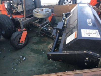
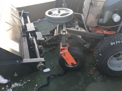
Continued on with my power broom project from here (https://www.hobby-machinist.com/thr...you-make-in-your-shop-today.67833/post-648864).

Well, we got too much snow (about 3") to use the broom on it on Friday, but I did get a chance to try it out on a driveway that was mostly cleared (I had done it with my plow, but it had been driven on, so it was a little uneven, so there was still some snow to clear). The broom itself worked very well, didn't leave any streaks behind (the Ariens Power Brush will leave some down the middle because it's got a gearbox in the middle of the brush), the engine didn't bog down at all and the belts didn't seem to slip at all.

So, as a incomplete prototype, it worked ok. I would say the main negative thing is that it is a little longer than I would like, as it will be tricky to get both it and my plow unit onto the trailer at the same time, and be able to load and unload them reasonably quickly.

Some pics of it:
290196
290197

Now to begin the long list of stuff to make it work right/better:
-hydro controllers need to be rebuilt/fixed (unit will drive forward or backward sometimes when "parked")
-engine leaks oil
-engine surges, likely doesn't start well when it's chilly out (ie, -25C)
-fab up an angling mechanism that can be worked from the operators position
-raise the operators controls about 5-6 inches (I'm 6'5", and they are just way to low for me)
-change the pto switch to an rocker-style switch, that can be operated without needing to "park" the controls
-make an electrically-operated (either via an actuator or a winch) method for raising/lowing the broom, that doesn't interfere with the caster wheels, that can be operated without needing to "park" the controls
-add about 100 lbs to the rear of the drive unit, for traction when the broom is raised
-replace tubes and bearings in front wheels
-get a second set of rear wheels with snow tires on them, and replace existing tires (they are pretty cracked from sitting in the sun, and one tire went flat in just a couple days, I had to fill the tire up to try it out today, after I had checked/filled the tires on Thursday)
-add some tie-down points for transport

Easy peasy.
 
Back
Top