- Joined
- Mar 21, 2013
- Messages
- 4,073
OK, so here's one of the things I accomplished in the shop today, a x-axis power feed install on my PM25. This will also work on the PM20, and the G0704 as well.
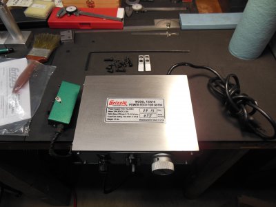
Unpackaged and laid out on the bench.
Remove the hand wheel and end plate from the left side of the table. You have to remove the key from the leadscrew then re-install after getting the end plate off.
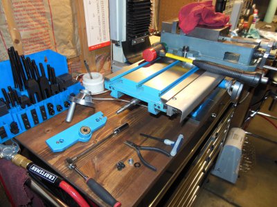
Then you remove the lower cover on the power feed. Checked out the engagement/disengagement mechanism. I may use a similar mechanism on another project for my lathe. Always learning something.
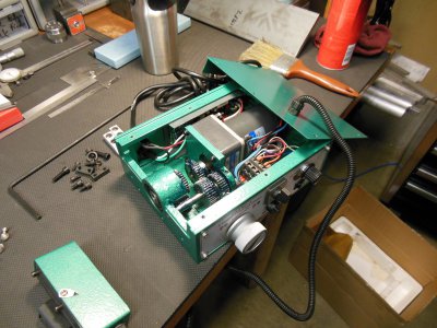
Because I installed my x-axis glass scale to the front of my table, I wasn't going to be using the limit switches. I don't take my hand off the power feed when it's running anyway, so a crash is unlikely (well, one hasn't happened yet...). I pulled apart the switch box and checked the switches which are NC types (normally closed).
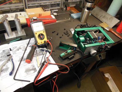
So, I cut the wires to the switches, and wrapped them in a wire nut.
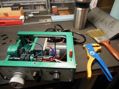
I put a small zip tie on the wires for some reason. Didn't want them putting any tension on the nut? Seemed like a good idea at the time... :headscratch:
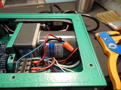
I will keep the limit switch. You just never know.
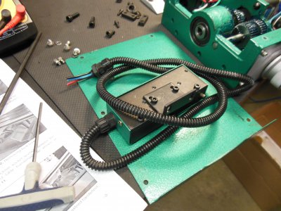
I was reading on another forum where a couple guys had installed these things and really complained about getting the box mounted to the end of the table. The directions just show a pic of a hand trying to get the allen head screws up into the box and threaded into the table. I can see where THAT would be a real pain. Especially with my big paws. When unpacking the unit, I pulled a really long allen wrench out of the box, stared at it for a second, then put it down. I remembered it, picked it up, and laid it on the box and went hmmmm...... There is a small removable plate on the end of the box, and then it occurred to me to just remove the plate and try using the long allen wrench to install the screws. Probably why they put it in the box, but there was NO mention of doing any of this in the instructions. Good thing I saw this thing laying in the bottom of the box!
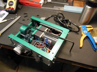
With the end cover removed and the long allen wrench, installing this thing onto the table took less than 5 min. Reason it took that long was my first attempt was to try putting the allen screw on the end of the wrench and try guiding it through the wires, switches, and gears in this little box. That was stupid... So, I removed the box from the leadscrew, put the allen head screws through the holes in the box FIRST, then slid it back on the leadscrew. Fish the allen wrench through the box and tighten the screws. No prob. :whistle:
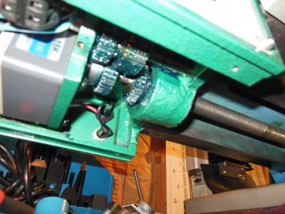
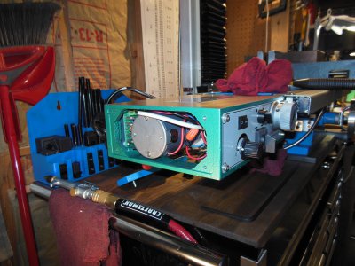
Got it on there, plugged it in, and (wait for it...) NO WORKIE! anic:
anic:
No, I didn't test it on the bench before I installed it. Honestly, I didn't think of that. So as I was contemplating what to do next and turning the immediately surrounding air a light shade of blue, I noticed the front panel is held on by four screws. Removed said screws, and gently removed the panel. Two wires were not connected to anything, and many of those that were on, were very loose on the spades. A bit of headscratching and reading the schematic in the back of the manual and I figured out where to connect the wires. Then I went around and gently put a bit of a crimp on the spade connectors I could get to.
All of a sudden, it works! Amazing how that happens.:whistle:
So anyway, here it is installed. Pretty easy to do, especially with the supplied extra length allen wrench. Wouldn't have hurt to mention what it was for in the directions though.
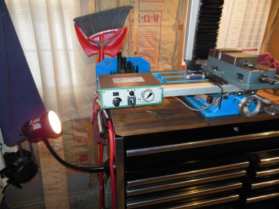
Hey, it could have been worse I guess. )
)
Bill


Unpackaged and laid out on the bench.

Remove the hand wheel and end plate from the left side of the table. You have to remove the key from the leadscrew then re-install after getting the end plate off.

Then you remove the lower cover on the power feed. Checked out the engagement/disengagement mechanism. I may use a similar mechanism on another project for my lathe. Always learning something.

Because I installed my x-axis glass scale to the front of my table, I wasn't going to be using the limit switches. I don't take my hand off the power feed when it's running anyway, so a crash is unlikely (well, one hasn't happened yet...). I pulled apart the switch box and checked the switches which are NC types (normally closed).

So, I cut the wires to the switches, and wrapped them in a wire nut.

I put a small zip tie on the wires for some reason. Didn't want them putting any tension on the nut? Seemed like a good idea at the time... :headscratch:

I will keep the limit switch. You just never know.

I was reading on another forum where a couple guys had installed these things and really complained about getting the box mounted to the end of the table. The directions just show a pic of a hand trying to get the allen head screws up into the box and threaded into the table. I can see where THAT would be a real pain. Especially with my big paws. When unpacking the unit, I pulled a really long allen wrench out of the box, stared at it for a second, then put it down. I remembered it, picked it up, and laid it on the box and went hmmmm...... There is a small removable plate on the end of the box, and then it occurred to me to just remove the plate and try using the long allen wrench to install the screws. Probably why they put it in the box, but there was NO mention of doing any of this in the instructions. Good thing I saw this thing laying in the bottom of the box!

With the end cover removed and the long allen wrench, installing this thing onto the table took less than 5 min. Reason it took that long was my first attempt was to try putting the allen screw on the end of the wrench and try guiding it through the wires, switches, and gears in this little box. That was stupid... So, I removed the box from the leadscrew, put the allen head screws through the holes in the box FIRST, then slid it back on the leadscrew. Fish the allen wrench through the box and tighten the screws. No prob. :whistle:


Got it on there, plugged it in, and (wait for it...) NO WORKIE!
No, I didn't test it on the bench before I installed it. Honestly, I didn't think of that. So as I was contemplating what to do next and turning the immediately surrounding air a light shade of blue, I noticed the front panel is held on by four screws. Removed said screws, and gently removed the panel. Two wires were not connected to anything, and many of those that were on, were very loose on the spades. A bit of headscratching and reading the schematic in the back of the manual and I figured out where to connect the wires. Then I went around and gently put a bit of a crimp on the spade connectors I could get to.
All of a sudden, it works! Amazing how that happens.:whistle:
So anyway, here it is installed. Pretty easy to do, especially with the supplied extra length allen wrench. Wouldn't have hurt to mention what it was for in the directions though.

Hey, it could have been worse I guess.
Bill


