Radius to a flat on a Rotary table - Order of Operation?

Well now that I have a better understanding of how to make the part. How would I set up to drill and tap these holes?

Screenshot 2023-06-28 214251.png
 
You will need to find out where they are from the edge, they look offset.
 
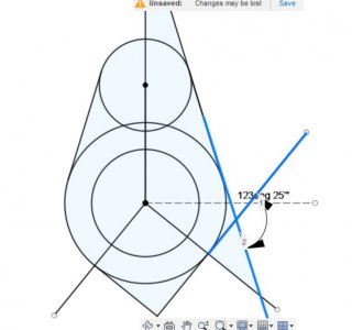
Start with your triangles. You would likely have to make a custom angle block or sine bar if going for an exact placement. The complimentary angle to the almost 123 angle shown is 57. Reference the 17 degree side plus the angle block to get the hole to be drilled perpendicular to the spindle. touch off on the big end and move over 30 mm (plus 1/2 diam of edgefinder) Capture.JPG
 
I figured 68°, setup a vice stop, center it front to back, drill and tap, flip the part and repeat.
 
Just because there is always more than one way to do things.....

Since your RT appears to be a Horizontal / Vertical.

You can just tip the RT up vertical, Rotate 51°, drill and tap.

There are still more ways to get it done.......

If you were really sneaky, You could bore the holes in the blank and then set it up on the vertical RT to mill the contour of the small end first, reset for the large end, then mill the rest of entire contour and then be able to drill and tap the holes all in the same setup.
 
Well, I haven't played with the rotary table since I finished my part the hard way. Other than marking the locations for drilling and tapping the holes. I decided to only drill one hole as really that is all that is needed for this application. I basically lined it up by eye as to where to drill the hole straight through. Until Elon Musk reaches out to me to build rocket parts, this will have to work.

I really need more practice / knowledge on this subject. I thought about turning my rotary up on end, but I would need to space the part out from the table or have a long drill bit and tap to complete the job.

Thanks for all the help guys.

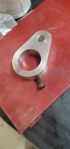
Here is the finished product. "Tailstock DRO" https://www.hobby-machinist.com/threads/tims-tailstock-dro-for-pm1236t.106982/

20230702_154223.jpg
 
Came out very nice.
This would have been easier using a cross-slide rotary table such as this battered old Troyke:
1688491709524.png
 
Even sitting on a fork lift that thing looks heavy.

I still have the old cheap "X" "Y" table that I had for my drill press before I knew better and got a mill, I have bolted that down onto the RT for things like this.
 
Rather than using set screws to mount to the tailstock quill, I used a split ring clamp. I mounted the clamp on the very 4end of the quill so as not to lose any travel. The clamp works very well.
1688573837063.png
 
Back
Top