

This grinder is a polish 1960s make Jotes Spc20a. It's spindle is somewhat unusual so I decided to document my effort to rebuild it here. Hopefully it will prove useful to anyone trying to do the same in future and interesting for others ")
I've had this surface grinder for years and I can achieve very good finishes on it, but I always felt it took way too long for the surface finish to cleanup. Also to get good finish it requires a long warmup (likewise for truing a new grinding wheel).
So recently I started investigating and I found runout exceeds the limit for this machine (twice when hot, 4 times when cold). I disassembled the spindle and I found many issues with it.
Also the wheel hub thread was bent when I bought it. I always wanted to straighten it. A spindle rebuild is a good opportunity to do that.
I was hoping to remove the spindle entirely(it's a tube-like unit). Unfortunately it wasn't possible. I suspect because of corrosion.
Here we have few photos of the disassembled spindle and a drawing showing it's layout. It runs at 2700rpm and it uses very light oil (iso 4).
The outer taper and spindle housing tube:

The shaft with two roller bearings. Note the oil groove cut in the shaft, not the bronze bushing.

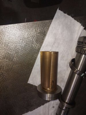
The bronze bushing, note unusual shape and the fact it is not split. That is very weird. It will certainly get deformed and it will contact only on three points! I guess that's fine?


Finally the drawing:

It is a nice design overall. It uses rubber clutch in the back and the pulley has its own bearings separate from the spindle this way the pulling force is not transferred to the spindle.
Many people modify this spindle for modern roller/ball bearings, but I enjoy my machines in their original configuration so I'll do my best to restore it leaving bearing swap as the final option (if everything else fails).
I started by indicating the shaft. It isn't easy (it took me a while to figure it out) as both centres are mangled. The front is on the bent thread, the rear has been drilled and tapped for a screw. In the process it got 20 thou (half a mm) off :-(
This is why I thought the shaft was bent, but thankfully it isn't.
Eventually I found a way using a lathe, a 4 jaw chuck and a steady rest.

I've managed to indicate it to 5micron runout (a bit over a tenth). Then I confirmed the shaft is straight. The taper is 0.01mm bent (4 tenths) which is sort of acceptable, but the thread was bent by almost 40 thou (a mm).
This is the setup I ended up using on the press. Sorry for a busy picture. The silver pucks are lead ingots used as padding to prevent the shaft from getting damaged.

Despite the indicators it was extremely difficult to measure how much the shaft deflects and how much it moves sinking into lead pucks. However I found a great method. I put the nut on the thread and I used gauge blocks tightening it so a block is grabbed. Then I could determine the movement by trying to insert the block between the nut's back and the front of the taper.
I managed to get it down to 0.2mm (a bit under a thou) which I decided is acceptable. Also I'm very happy I managed not to bend the shaft in the process
I've had this surface grinder for years and I can achieve very good finishes on it, but I always felt it took way too long for the surface finish to cleanup. Also to get good finish it requires a long warmup (likewise for truing a new grinding wheel).
So recently I started investigating and I found runout exceeds the limit for this machine (twice when hot, 4 times when cold). I disassembled the spindle and I found many issues with it.
Also the wheel hub thread was bent when I bought it. I always wanted to straighten it. A spindle rebuild is a good opportunity to do that.
I was hoping to remove the spindle entirely(it's a tube-like unit). Unfortunately it wasn't possible. I suspect because of corrosion.
Here we have few photos of the disassembled spindle and a drawing showing it's layout. It runs at 2700rpm and it uses very light oil (iso 4).
The outer taper and spindle housing tube:
The shaft with two roller bearings. Note the oil groove cut in the shaft, not the bronze bushing.
The bronze bushing, note unusual shape and the fact it is not split. That is very weird. It will certainly get deformed and it will contact only on three points! I guess that's fine?
Finally the drawing:
It is a nice design overall. It uses rubber clutch in the back and the pulley has its own bearings separate from the spindle this way the pulling force is not transferred to the spindle.
Many people modify this spindle for modern roller/ball bearings, but I enjoy my machines in their original configuration so I'll do my best to restore it leaving bearing swap as the final option (if everything else fails).
I started by indicating the shaft. It isn't easy (it took me a while to figure it out) as both centres are mangled. The front is on the bent thread, the rear has been drilled and tapped for a screw. In the process it got 20 thou (half a mm) off :-(
This is why I thought the shaft was bent, but thankfully it isn't.
Eventually I found a way using a lathe, a 4 jaw chuck and a steady rest.
I've managed to indicate it to 5micron runout (a bit over a tenth). Then I confirmed the shaft is straight. The taper is 0.01mm bent (4 tenths) which is sort of acceptable, but the thread was bent by almost 40 thou (a mm).
This is the setup I ended up using on the press. Sorry for a busy picture. The silver pucks are lead ingots used as padding to prevent the shaft from getting damaged.
Despite the indicators it was extremely difficult to measure how much the shaft deflects and how much it moves sinking into lead pucks. However I found a great method. I put the nut on the thread and I used gauge blocks tightening it so a block is grabbed. Then I could determine the movement by trying to insert the block between the nut's back and the front of the taper.
I managed to get it down to 0.2mm (a bit under a thou) which I decided is acceptable. Also I'm very happy I managed not to bend the shaft in the process


 I'm very pleased with the results. But first let's talk about the final stuff I did. I'm pleased to say after straightening the threaded piece in front of the nose the nut actually threads all the way


