

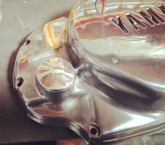
To effect the modifications for inclusion of a remote, spin on filter and cooler, I had to modify the right side engine cover. The oil pump is located inside this cover.
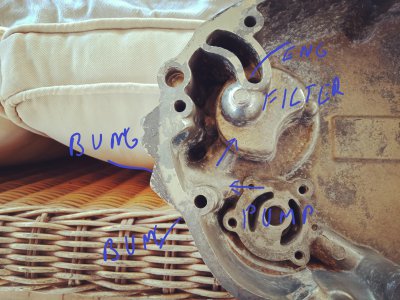
The oil galley from the pump is 10mm and is drilled at a weird angle to the cover. Halfway along it is cross drilled at a right angle, both of these holes are plugged with a blanking bung at the front of the cover. The cross drilled hole leads to the stock filter behind the cover on the side of the engine side cover. So, the pump pumps oil up the 10mm hole, does a right turn into the cross drilled hole and on to the filter, then on through the engine.
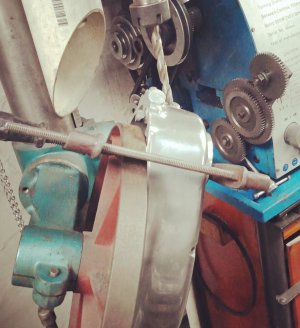
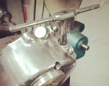
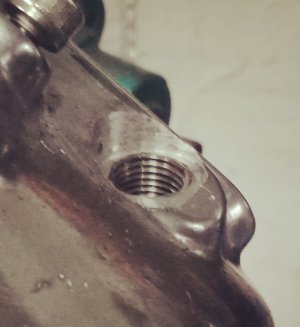
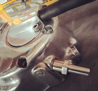
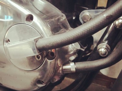
So, in order to fit a remote, spin on filter, I had to remove the bung to the 10mm hole on the front of the cover, drill the 10mm hole out to 10.8mm and thread with a 12mm tap to a depth of 40mm. I then turned up a stainless, threaded barb to suit and the threaded section when screwed in place, covers the cross drilled hole, thus bypassing the stock filter in the side of the cover. So the pump now pumps oil up the 10mm hole in the cover, through the threaded barb and then on to a remote spin on filter, via a rubber hose.. The oil enters the filter and then exits that and continues on to the cooler. From there it flows to the replacement filter cover I machined up, into the filter housing behind the cover, which is now empty, then on to the engine. Sounds complicated, but it’s not really. The spin on filter does a better job than the stock filter as the stock filter is really only a strainer.
Mounting the side cover on the drill table was a job and a half, as the hole to the oil pump is off skew on two axis’. Once I’d drilled and tapped the 10mm hole, because of the weird angle the hole exits the cover, it’s not square to the surface, so I had to square the surface up and countersink it to accept an O ring to seal the barb using a modified router bit.
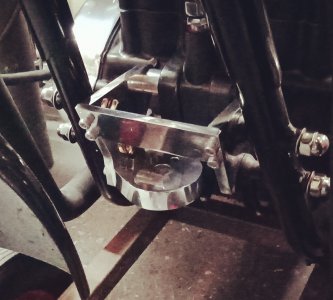
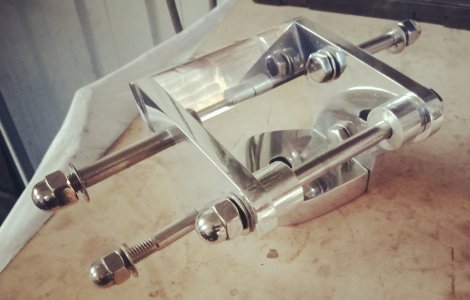
The new filter has a different mount to the other, so I had to bend up some 3mm ally for a mount. This engine is a shaker, so I decided to mount the cooler in rubber. Unfortunately, grommets of this size are only available to fit 1.5 mm thick material, so had to mill the 3mm ally down to 1.5 around the grommet hole so the grommet would fit. I also had to cut four pieces of ally tube between top and bottom cooler mounts.
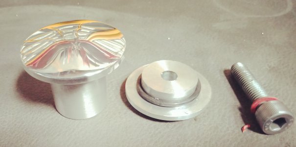
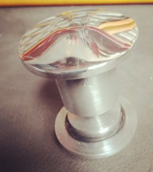
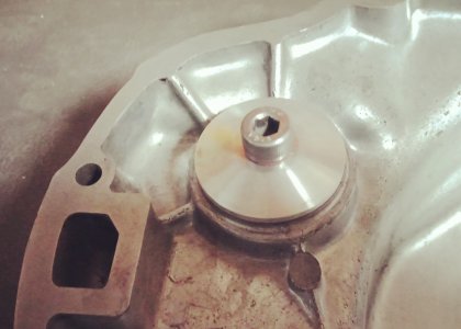
Whilst I had the engine cover off, I removed the kickstart mechanism and machined up a two piece aluminium bug to fit in the kickstart lever hole. The bung has O rings inside and out to prevent leaks, as well as the original seal.
Lots and lots of work, but it’s done
The oil galley from the pump is 10mm and is drilled at a weird angle to the cover. Halfway along it is cross drilled at a right angle, both of these holes are plugged with a blanking bung at the front of the cover. The cross drilled hole leads to the stock filter behind the cover on the side of the engine side cover. So, the pump pumps oil up the 10mm hole, does a right turn into the cross drilled hole and on to the filter, then on through the engine.
So, in order to fit a remote, spin on filter, I had to remove the bung to the 10mm hole on the front of the cover, drill the 10mm hole out to 10.8mm and thread with a 12mm tap to a depth of 40mm. I then turned up a stainless, threaded barb to suit and the threaded section when screwed in place, covers the cross drilled hole, thus bypassing the stock filter in the side of the cover. So the pump now pumps oil up the 10mm hole in the cover, through the threaded barb and then on to a remote spin on filter, via a rubber hose.. The oil enters the filter and then exits that and continues on to the cooler. From there it flows to the replacement filter cover I machined up, into the filter housing behind the cover, which is now empty, then on to the engine. Sounds complicated, but it’s not really. The spin on filter does a better job than the stock filter as the stock filter is really only a strainer.
Mounting the side cover on the drill table was a job and a half, as the hole to the oil pump is off skew on two axis’. Once I’d drilled and tapped the 10mm hole, because of the weird angle the hole exits the cover, it’s not square to the surface, so I had to square the surface up and countersink it to accept an O ring to seal the barb using a modified router bit.
The new filter has a different mount to the other, so I had to bend up some 3mm ally for a mount. This engine is a shaker, so I decided to mount the cooler in rubber. Unfortunately, grommets of this size are only available to fit 1.5 mm thick material, so had to mill the 3mm ally down to 1.5 around the grommet hole so the grommet would fit. I also had to cut four pieces of ally tube between top and bottom cooler mounts.
Whilst I had the engine cover off, I removed the kickstart mechanism and machined up a two piece aluminium bug to fit in the kickstart lever hole. The bung has O rings inside and out to prevent leaks, as well as the original seal.
Lots and lots of work, but it’s done
Attachments
-
 a.jpg594.2 KB · Views: 14
 -
 b.jpg481.2 KB · Views: 12
 -
 c.jpg296 KB · Views: 12
 -
 d.jpg782.9 KB · Views: 13
 -
 e.jpg641.1 KB · Views: 12
 -
 f.jpg491.5 KB · Views: 9
 -
 g.jpg510.2 KB · Views: 9
 -
 h.jpg458.7 KB · Views: 8
 -
 i.jpg825.9 KB · Views: 9
 -
![IMG20210905100516[1].jpg](/data/attachments/334/334611-c3f84a69e0ffa95cf895f4c71acb6d4e.jpg) IMG20210905100516[1].jpg2.8 MB · Views: 9
IMG20210905100516[1].jpg2.8 MB · Views: 9 -
 IMG20210714161801.jpg643.6 KB · Views: 11
 -
 IMG20210714155431.jpg705.9 KB · Views: 10
 -
 IMG20210905100408.jpg2.6 MB · Views: 14