Rewiring Emco Maximat mentor 10 from 440 Volt to 220 Volt

Wheresmywrench?

Active User
Registered
Joined
May 26, 2014
Messages
183
I was given a Emco Maximat Mentor 10 lathe/mill combo, has a bad gear. It is 3phase 440volt. I have replacement 220v single phase Emco Maximat V10 motors for the mill head and the lathe. I need to rewire the machine from 3 phase to single phase. Are there any wiring diagrams that show where to make the connections to do this? :whistle:
 
There's a V10 group over at YahooGroups, and there's been quite a lot of discussion of the wiring, over the past couple of years. Someone probably has done this and posted about it. Check that bunch out, and esp. the archives on that list.
 
Hi Pete, first thing to look at, is there a control transformer with 240 & 480 volt primary winding jumpers? Hopefully so; change them to 240V. I don't have a schematic to look at so this is all general advice. All the motor overload relay heaters are rated for the motor full load currents when operated at 480 V, 3-phase; full load current for single-phase motors running at 240V will be more than twice that amount so they must be sized accordingly. Hopefully you can find an overload relay chart for your motor starter so you can match them to your new motors. Hope this helps.
 
OK I'm going to switch out the 440v 3 phase motors for 220v single phase motors. I am then going to rewire the electrical control box as the single phase motors do not use as many connection points as the 3 phase motors do. Also going to use a step up transformer to supply 440v for the magnetic contactors to operate. I have a transformer to do this on hand. This being a Maximat Mentor it does not have push buttons but has rotary switches.
 
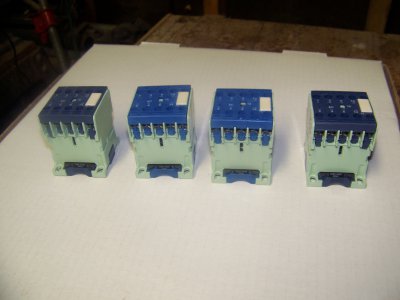
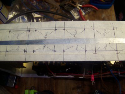
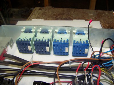
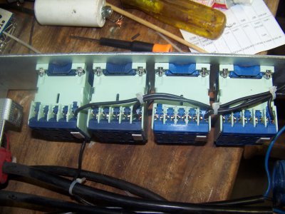
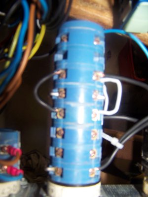
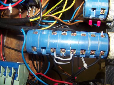
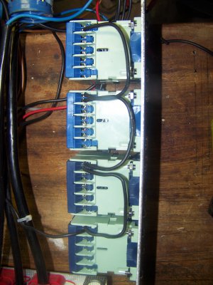
Update on my rewiring of my Maximat V10-P Mentor. I have tossed the 440v transformer idea and bought new magnetic contactors with 220V coils. Replaced the main contactor. Then gave up on the rewiring of the switch just couldn't get the right combination of wires. So I have used the switch the run 4 small contactors which will do the switching for me. So I have 1 for the Forward, 1 for Reverse, 1 for Slow Speed, and 1 for Fast Speed.
The jumpers are just temporary for now. I'll tin them for the final assembly once I'm satisfied everything is working as I intend. I'll do a dry test to make sure the relays all function in the proper sequence before I connect the motor to the contactors. Also since I will only be using 1 single phase motor the run capacitor will be mounted inside the connector box.


100_3806.JPG 100_3807.JPG 100_3810.JPG 100_3812.JPG 100_3813.JPG 100_3815.JPG 100_3816.JPG
 
Good day all,
I have a similar problem with my V10 p mentor lathe, 220 volt single phase, the electrics. I am not an electrician AT ALL.
So, having said that, am assembling lathe got all the wiring back as was ??!! thank goodness for colour coding. I have 4 black wires from the rotary switch box to lathe motor loom that sits on the back of lathe above motor [in a box]. I think that they are reverse and forward and 2 speeds can anyone suggest how to identify what goes where or put another way which black wire goes to which black wire. Realize this is bit of an open ended question and lacks specifics but I think there are lot out there who are very knowledgeable in this area. I too had no luck with the Yahoo link cannot even get on.
With thanks Golfpin
 
Well, I assume the wires are still connected to the connector box? If so do you have a copy of the Instruction Manual? If you do at the end of of the manual it should list where each of the wires that come from the motor go. The connections in the box are 1 thru 12 from left to right and the book should show the connection points based on the color of the wires from the motor. If you don't give me the colors from the motor wires, colors may be different depending on when the motor was manufatured.
 
Back
Top