- Joined
- Oct 15, 2020
- Messages
- 208
Pictures first, story next.
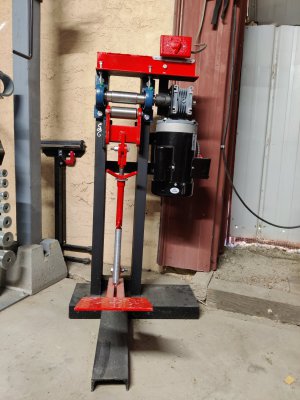
(The frame is NOT crooked, it's a camera angle thing)


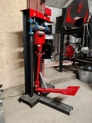
It is my variation on the Hugh McDonald Rolling Mill.
I didn't bother with the cam mechanism at the bottom of the over-center lever, as it strikes me as unecessary.
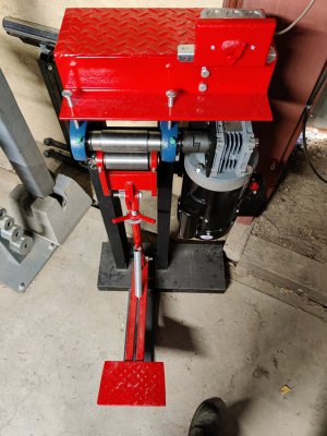
Rather than putting the lower die on a swing arm, I made a carriage that is constrained by means of two 1/2" shoulder bolts on either side; this arrangement allows for the dies to intercept the work at the same point, without regard to width of the stock being rolled out. In the traditional variety, the swing arm arrangement makes an arc (obviously) that causes the intercept point to move, necessitating the work being held at an angle. Does this matter? Probably not!
The thing is framed with certified grade-A scrapbinium steel. The dies are unknownium, though likely cold-rolled, with 4130 "tires" pressed over them, then welded. I then hardened the dies (1hr @1650, water-quench) and ground to within 0.0005" TIR on my Jet T&C with spindle and tailstock.
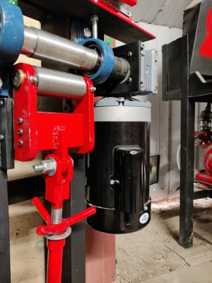
The lower die carriage works via some flanged 3/4" oilite bushings with zerks because zerks are zerky. The upper die is held via 1.500" cast-iron pillows.
The motor is a TEFC 1hp 120VAC motor with a 56C flange, and the worm is bolt-on 80:1; total RPM calculates to ~21. Had to use a shaft coupler to account for the horrifying reality of lining up shafts in a rigid setup.
It was a relatively straight-forward design, and not really a difficult build, but the sliding carriage required more fit-fack-fix than I want to admit, and the over-center lever is strong enough to flex the whole frame when it is at its tightest setting (rolls in contact). I can probably put some strong-back-gussets in the base member, as it is a big chunk of C channel, and appears to be where the flex originates (in the web). I don't think that I need to, but none of us really need to be doing anything we do here.
The worm box was a chore to find. The prices have gotten BEYOND INSANE - I found a great one that would have cost more than the whole project itself, but I went with this one (JIE) that was only a little more than the motor. I am a little worried about it as I could not find a HP rating for it (manu. only rates a range of 1/3 - 30hp for the whole product line!). It is an aluminum body (steel gears obviously) and the documentation was... not good. It works though. Making the 2.375" hole for its flange was weird - I don't have annulars, a boring head would still be boring it, and the biggest bit I have is 1". Also, my Rotab is only 4", so I ended up putting it in the 3 jaw chuck on my BS-0 Dividing head, set vertical and with shims in the chuck to make 3 jaws clamp evenly on a square. Cut it on the circumference with a 1/2" endmill.
By far the worst part was hardening. I don't have any tool-wrap-foil, and the 4130 I found (seamless tube) was only 0.098" wall, so I was really worried about decarb. I coated it in clay (ancient Chinese secret) and the clay kept cracking - recoat and dry - crack - recoat..... It worked though, so now I've got a bunch of ceramic chucks that I can grind up and mix with the next batch as a grog (supposed to prevent cracking).
The lower die has two nubs to work in the oilite bushings, and hard is better for journals. As the unknownium rod that I had was likely cold-rolled, I mixed up some case-hardening-clay (salt-flour dough with charcoal dust) and packed it around the journals before coating in clay.
Did it work? Not really, maybe kinda? Spark tests were inconclusive (saw some tails, but not like I am used to seeing on tool steels) I'm done messing with that alchemy on this project.
Why 4130? Because a rod of 2" H13 was too much, 4140 was INSANE, and 4130 is supposed to be tough and get around 46-50 RC. If the dies fail, I know the guy who made them, so I can write him a strongly worded email
Thickest stock I can do on it is around 2" (maybe 1.5") - I don't know, and don't plan on rolling out super thick stuff. As the rolls can touch, the thinnest I can roll out would be something akin to gold-leaf. Dies have 3.750" of real-estate to work with, and with their small diameter (~1.750") I can get some nasty forces on the work (provided I hard-back the frame).
In any case, here is the newest member of the crew: Say hello to Ms. Rollberta!
Thanks for reading.
(The frame is NOT crooked, it's a camera angle thing)


It is my variation on the Hugh McDonald Rolling Mill.
I didn't bother with the cam mechanism at the bottom of the over-center lever, as it strikes me as unecessary.
Rather than putting the lower die on a swing arm, I made a carriage that is constrained by means of two 1/2" shoulder bolts on either side; this arrangement allows for the dies to intercept the work at the same point, without regard to width of the stock being rolled out. In the traditional variety, the swing arm arrangement makes an arc (obviously) that causes the intercept point to move, necessitating the work being held at an angle. Does this matter? Probably not!
The thing is framed with certified grade-A scrapbinium steel. The dies are unknownium, though likely cold-rolled, with 4130 "tires" pressed over them, then welded. I then hardened the dies (1hr @1650, water-quench) and ground to within 0.0005" TIR on my Jet T&C with spindle and tailstock.
The lower die carriage works via some flanged 3/4" oilite bushings with zerks because zerks are zerky. The upper die is held via 1.500" cast-iron pillows.
The motor is a TEFC 1hp 120VAC motor with a 56C flange, and the worm is bolt-on 80:1; total RPM calculates to ~21. Had to use a shaft coupler to account for the horrifying reality of lining up shafts in a rigid setup.
It was a relatively straight-forward design, and not really a difficult build, but the sliding carriage required more fit-fack-fix than I want to admit, and the over-center lever is strong enough to flex the whole frame when it is at its tightest setting (rolls in contact). I can probably put some strong-back-gussets in the base member, as it is a big chunk of C channel, and appears to be where the flex originates (in the web). I don't think that I need to, but none of us really need to be doing anything we do here.
The worm box was a chore to find. The prices have gotten BEYOND INSANE - I found a great one that would have cost more than the whole project itself, but I went with this one (JIE) that was only a little more than the motor. I am a little worried about it as I could not find a HP rating for it (manu. only rates a range of 1/3 - 30hp for the whole product line!). It is an aluminum body (steel gears obviously) and the documentation was... not good. It works though. Making the 2.375" hole for its flange was weird - I don't have annulars, a boring head would still be boring it, and the biggest bit I have is 1". Also, my Rotab is only 4", so I ended up putting it in the 3 jaw chuck on my BS-0 Dividing head, set vertical and with shims in the chuck to make 3 jaws clamp evenly on a square. Cut it on the circumference with a 1/2" endmill.
By far the worst part was hardening. I don't have any tool-wrap-foil, and the 4130 I found (seamless tube) was only 0.098" wall, so I was really worried about decarb. I coated it in clay (ancient Chinese secret) and the clay kept cracking - recoat and dry - crack - recoat..... It worked though, so now I've got a bunch of ceramic chucks that I can grind up and mix with the next batch as a grog (supposed to prevent cracking).
The lower die has two nubs to work in the oilite bushings, and hard is better for journals. As the unknownium rod that I had was likely cold-rolled, I mixed up some case-hardening-clay (salt-flour dough with charcoal dust) and packed it around the journals before coating in clay.
Did it work? Not really, maybe kinda? Spark tests were inconclusive (saw some tails, but not like I am used to seeing on tool steels) I'm done messing with that alchemy on this project.
Why 4130? Because a rod of 2" H13 was too much, 4140 was INSANE, and 4130 is supposed to be tough and get around 46-50 RC. If the dies fail, I know the guy who made them, so I can write him a strongly worded email
Thickest stock I can do on it is around 2" (maybe 1.5") - I don't know, and don't plan on rolling out super thick stuff. As the rolls can touch, the thinnest I can roll out would be something akin to gold-leaf. Dies have 3.750" of real-estate to work with, and with their small diameter (~1.750") I can get some nasty forces on the work (provided I hard-back the frame).
In any case, here is the newest member of the crew: Say hello to Ms. Rollberta!
Thanks for reading.


