Simple Tailstock Travel Indicator

Micke S

Active User
Registered
Joined
Oct 9, 2014
Messages
465
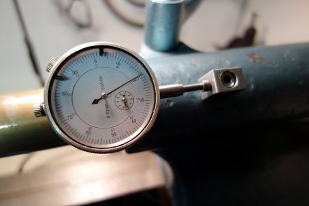
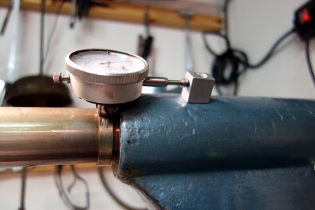
I was inspired by Mark F to make a tailstock travel indicator. This one is no near as nice as his, but it works fine and is easy to fabricate. It feels somewhat embarrassing to make an item based on his idea, but it is missed feature so it is how it is. The dial is mounted on a rigid tube clamp that can be locked anywhere on the quill. I only needed to drill and thread for the reference stop, which is made of T6 aluminium. The clamp and the dial locks with the same screw. It would be better to make a longer screw and have a 1 1/2" knurled dial on the end to eliminate the need for a tool to lock with.
DSC03511.JPG

DSC03509.JPG

DSC03509.JPG DSC03511.JPG
 
I was inspired by Mark F to make a tailstock travel indicator. This one is no near as nice as his, but it works fine and is easy to fabricate. It feels somewhat embarrassing to make an item based on his idea, but it is missed feature so it is how it is. The dial is mounted on a rigid tube clamp that can be locked anywhere on the quill. I only needed to drill and thread for the reference stop, which is made of T6 aluminium. The clamp and the dial locks with the same screw. It would be better to make a longer screw and have a 1 1/2" knurled dial on the end to eliminate the need for a tool to lock with.

View attachment 91130

View attachment 91129

I like it, it is clean and simple.
 
I forgot to deburr the hole on the stopper. This will be done. And probably machine a aluminium clamp since I want to make it fully hand-controlled. The clamp could also be wider to slide easy on the quill.
 
I was inspired by Mark F to make a tailstock travel indicator. This one is no near as nice as his, but it works fine and is easy to fabricate. It feels somewhat embarrassing to make an item based on his idea, but it is missed feature so it is how it is. The dial is mounted on a rigid tube clamp that can be locked anywhere on the quill. I only needed to drill and thread for the reference stop, which is made of T6 aluminium. The clamp and the dial locks with the same screw. It would be better to make a longer screw and have a 1 1/2" knurled dial on the end to eliminate the need for a tool to lock with.

View attachment 91130

View attachment 91129


NEVER, EVER feel bad about using, improving or changing my ideas. I am flattered to have inspired you and that is my purpose here. You are a perfect example of what I want to do. Show and inspire everyone to make what they need and have decent tooling for low cost. Thank you for paying attention and using what I put out there.

Thank you,

Mark Frazier
 
I've changed the approach so the solution didn't last for very long. Since I have a calibrated scale on the tailstock handwheel I don't need the extra dial even though it is much easier to read than counting segments and turns on the wheel scale. So instead it will be an adjustable 6 mm stainless steel bar on top of the tailstock, which will be set manually and serve as a quill stop at the desired location. The bar will run in a aluminium block and will be locked by a knurled dial. The bar tip is bent 1/4" 90 degrees at the end towards the headstock, so it stops the quill. When it is released and rotated 180 degrees it will ha no influence on the quill. I'll post a photo when it is done but you understand the principle if I was able to explain.

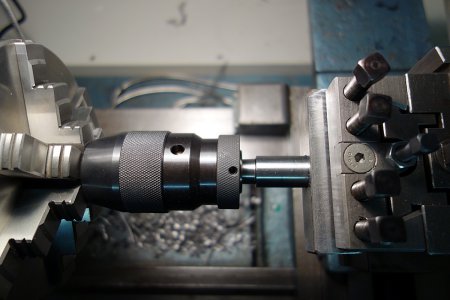
The focus today was instead directed to another solution for easy and precise measurement of boring deep. I'll use the QCTP as a chuck holder for light duty drilling up to 16 mm. By this I'm able to use the DRO as precision drill deep gauge. It is just to reset the DRO at the hole entry and stop the drilling when the desired deep is reached. The picture shows when the B16 to 20 mm adapter has been press fitted into a trued 30*30 mm chunk of steel and locked with Loctite permanent. In case it will ever come lose it is just to drill a hole and lock it with a machine screw. I don't want to use the MIG welder for this since such chunks needs a lot of current to be welded and there is a risk for slight bending. It may also be possible to precision enlarge holes with this solution if an end mill or small boring head is located on the chuck. At least for not too hard materials like aluminium.

The chuck is dialed in and will not be used until the Loctite 270 has cured 24 hours. Not that it should be needed but it is unnecessary to force this.

The chuck is centered on the toolpost to make the setup as rigid as possible. I see now that the distance between the chuck an toolpost bit is unnecessary long and should have been shortened about 1 inch to make it more rigid. The chuck taper is only MT2.

DSC03514.JPG

DSC03514.JPG
 
Back
Top