- Joined
- Jun 20, 2022
- Messages
- 207
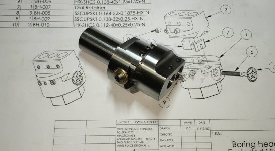
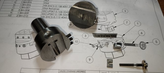
Made a small boring head for my mill/drill based on maching notes by Dean Williams, and plans by Steve Campbell. I do not know these gentlemen, but wish to give credit where due for the work they did.
The machining notes: http://www.deansphotographica.com/machining/projects/mill/boring/boring.html
The plans: http://www.deansphotographica.com/machining/projects/mill/boring/boringhead.pdf
‐----------------
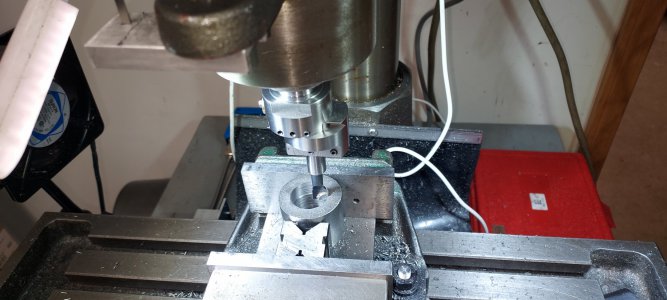
I won't bore you with the details of machining the boring head, except maybe point out some changes. The photos and notes at the website, along with plans provide plenty of detail. Mine needs some refinement and polishing, but works quite well otherwise.
----------------
I do want to add what I used to scribe the dial because I found a website with an online tool that makes custom degree wheels very easy to make.
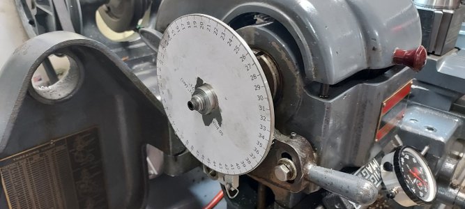
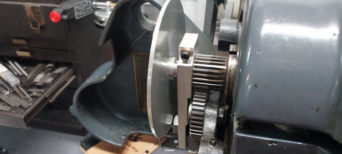
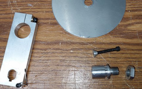
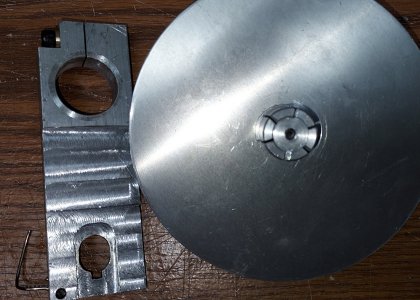
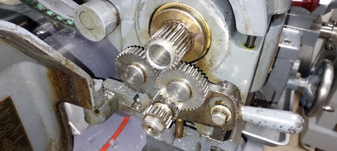
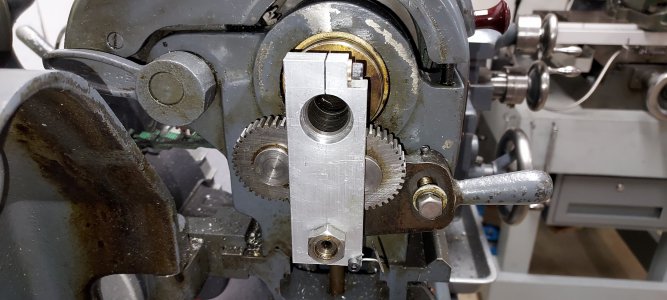
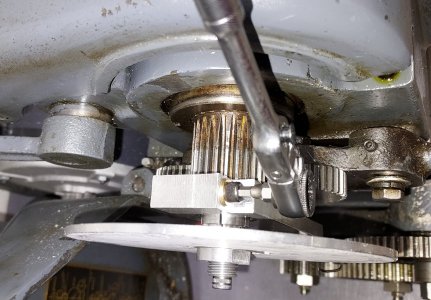
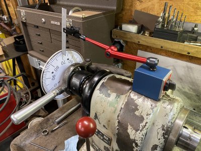
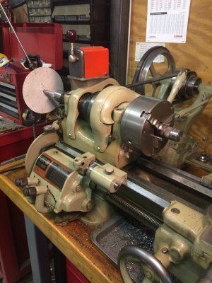
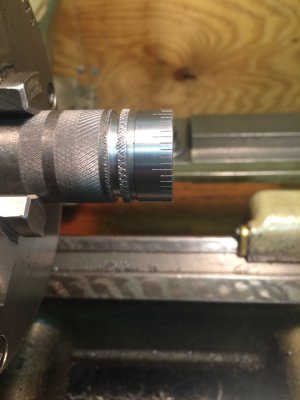
The divider is fairly self explanatory. A piece of AL plate turned to 5" diameter with a Joe Pie expanding mandrel attached to the center so it fits in the back of the spindle bore. A chunk of AL fixtures to the outside of the back of the spindle and then down to the stud where the stud gear usually resides. This also has a wire pointer. Long story short I was easily able to scribed 25 equal divisions and lock the spindle tightly in place with the socket head cap screw shown. This setup was a fairly easy morning project, and allows you to scribe divisions easily without a dividing head. I expect you could probably use something like it for cutting gears (the hard way!)
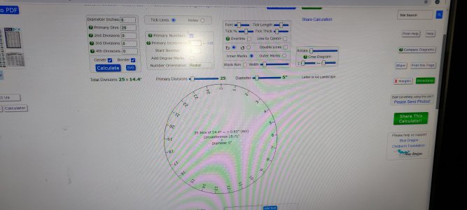
The actual dial is simply printed on computer paper. This website provides all the tools you need to make a fully customizable protractor, with custom divisions (50 in my case, only needed 25), and custom size. VERY VERY USEFUL:
 www.blocklayer.com
After that I just took some Super77 spray contact cement and stuck it on there.
____________________
My notes:
- The original design is for a Taig Mill. I made mine with a solid 7/8" stub shaft to go in my largest R8 collet. I find this to be the most convenient way to get tools into a mill drill.
- I used a piece of 1 5/8" 1144 stressproof rod to make the majority of the tool. I kept mine at 1.6" finished size, and LUCKY I did.
- I changed mine to use 1/2" boring bars. This is the clincher, I did not pay enough attention to spacing the holes. The original design only has about .450" of range. My tool holes were spaced .563" leave a BIG gap in the range. Luckily I was able to modify it by changing the pusher block, and extending the slot in order to get .580" of useful range.
_____________________
PAYING IT FORWARD:
THIS DESIGN USES A 6-40 CAPHEAD AS A LEADSCREW TO GET .025" PER TURN. THESE SCREWS ARE VERY HARD TO FIND. I HAD TO ORDER A BOX OF 25 FROM MCMASTER TO GET 1 SCREW. IF YOU TRULY WANT TO MAKE ONE OF THESE (ON YOUR HONOR) I WILL MAIL YOU A 6-40-1.25" SCREW FROM MY SUPPLY. IF ANYONE DOES THIS DM ME A MAILING ADDRESS AND I'LL PUT ONE IN AN ENVELOPE FOR YOU AND SEND IT OUT (WHILE SUPPLIES LAST, SUBJECT TO CANCELLATION AT ANY TIME!! LOL).
The machining notes: http://www.deansphotographica.com/machining/projects/mill/boring/boring.html
The plans: http://www.deansphotographica.com/machining/projects/mill/boring/boringhead.pdf
‐----------------
I won't bore you with the details of machining the boring head, except maybe point out some changes. The photos and notes at the website, along with plans provide plenty of detail. Mine needs some refinement and polishing, but works quite well otherwise.


----------------
I do want to add what I used to scribe the dial because I found a website with an online tool that makes custom degree wheels very easy to make.


The divider is fairly self explanatory. A piece of AL plate turned to 5" diameter with a Joe Pie expanding mandrel attached to the center so it fits in the back of the spindle bore. A chunk of AL fixtures to the outside of the back of the spindle and then down to the stud where the stud gear usually resides. This also has a wire pointer. Long story short I was easily able to scribed 25 equal divisions and lock the spindle tightly in place with the socket head cap screw shown. This setup was a fairly easy morning project, and allows you to scribe divisions easily without a dividing head. I expect you could probably use something like it for cutting gears (the hard way!)
The actual dial is simply printed on computer paper. This website provides all the tools you need to make a fully customizable protractor, with custom divisions (50 in my case, only needed 25), and custom size. VERY VERY USEFUL:
Circle Divider Templates - Inch
After that I just took some Super77 spray contact cement and stuck it on there.
____________________
My notes:
- The original design is for a Taig Mill. I made mine with a solid 7/8" stub shaft to go in my largest R8 collet. I find this to be the most convenient way to get tools into a mill drill.
- I used a piece of 1 5/8" 1144 stressproof rod to make the majority of the tool. I kept mine at 1.6" finished size, and LUCKY I did.
- I changed mine to use 1/2" boring bars. This is the clincher, I did not pay enough attention to spacing the holes. The original design only has about .450" of range. My tool holes were spaced .563" leave a BIG gap in the range. Luckily I was able to modify it by changing the pusher block, and extending the slot in order to get .580" of useful range.
_____________________
PAYING IT FORWARD:
THIS DESIGN USES A 6-40 CAPHEAD AS A LEADSCREW TO GET .025" PER TURN. THESE SCREWS ARE VERY HARD TO FIND. I HAD TO ORDER A BOX OF 25 FROM MCMASTER TO GET 1 SCREW. IF YOU TRULY WANT TO MAKE ONE OF THESE (ON YOUR HONOR) I WILL MAIL YOU A 6-40-1.25" SCREW FROM MY SUPPLY. IF ANYONE DOES THIS DM ME A MAILING ADDRESS AND I'LL PUT ONE IN AN ENVELOPE FOR YOU AND SEND IT OUT (WHILE SUPPLIES LAST, SUBJECT TO CANCELLATION AT ANY TIME!! LOL).
Last edited:


