- Joined
- Apr 1, 2015
- Messages
- 76
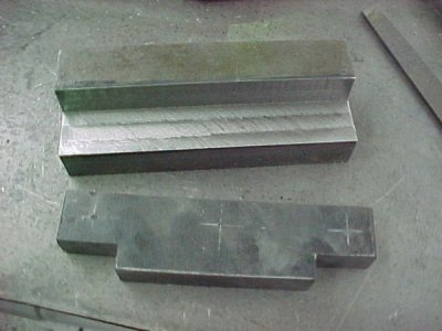
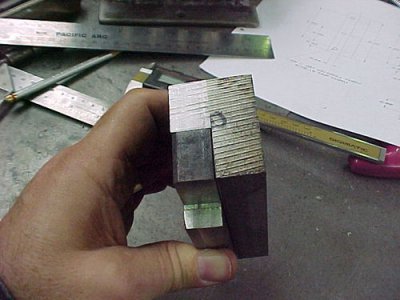
Using NiCop coiled brake line is pain only in trying to get it straight. I couldn't make myself spend 200 dollars on a 5 roller tubing straightener so I designed one in 3D CAD and built it in the shop.
I turned the rollers with a Vee Groove which will work with any size tubing up to 5/8th's of an inch. it works especially well with 3/16th's to 3/8th line.
This is the business side of the rig showing the five rollers.
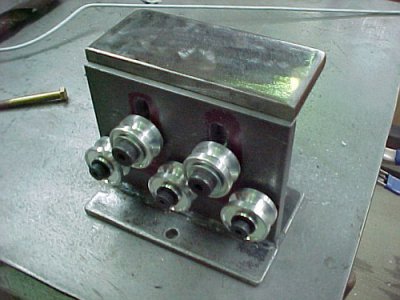
I still need to weld up the top plate but I did a proof of design and it works great!
Here is the back showing the adjustment block which carries the two upper rollers on some shoulder bolts.
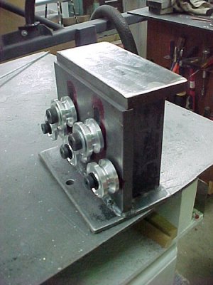
Once I finish the welding this bolt will get cut down and the tensioning knob will be attached to it.
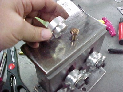
Turn the knob to raise or lower the rollers to fit the tube you are straightening and to set the tension on the tube as you straighten it.
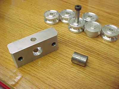
This is a pic of some of the pieces. The five rollers, tensinong knob and block and the trunnion I made so the aluminum block wouldn't have to be threaded. The trunnion carries all of the tensioning loads.
I'll post up pics after i get it welded and painted.
Mark
I turned the rollers with a Vee Groove which will work with any size tubing up to 5/8th's of an inch. it works especially well with 3/16th's to 3/8th line.
This is the business side of the rig showing the five rollers.

I still need to weld up the top plate but I did a proof of design and it works great!
Here is the back showing the adjustment block which carries the two upper rollers on some shoulder bolts.

Once I finish the welding this bolt will get cut down and the tensioning knob will be attached to it.

Turn the knob to raise or lower the rollers to fit the tube you are straightening and to set the tension on the tube as you straighten it.
This is a pic of some of the pieces. The five rollers, tensinong knob and block and the trunnion I made so the aluminum block wouldn't have to be threaded. The trunnion carries all of the tensioning loads.

I'll post up pics after i get it welded and painted.
Mark


