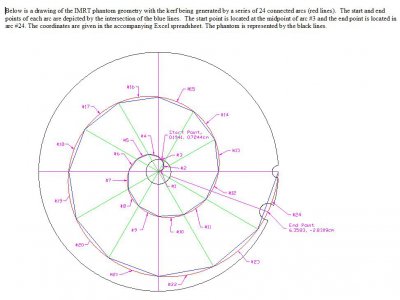
Spiral softjaw plate

Karl_T

H-M Supporter - Sustaining Member
H-M Platinum Supporter
Joined
Oct 14, 2014
Messages
1,979
This is the project to do the project...

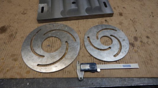
Need to bore soft jaws to hold the motor shaft for making the 10EE gearbox adaptor. Best way to do this is to clamp the jaws tight on a spiral plate. I have seen them for sale for big bucks. Here's one offer:
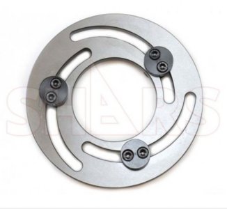
softjaw plate.JPG
Brain teaser for the day. How do you calculate a sprial? OK, any point on a circle can be calculated by X is sine angle times radius. Y is cosine angle times radius. So, if you increase the radius every degree of arc, a sprial is generated. Here's the excel spread sheet I worked out for one sprial thru 120 degrees.
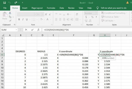
excel spiral calcs.JPG
 
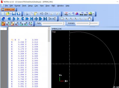
I saved the last four columns to a text file and opened the file in my backplotter - NC plot. It generates a Gcode route that can then be exported as a .dxf file.

NCPLOT SPRIAL PLATE.JPG


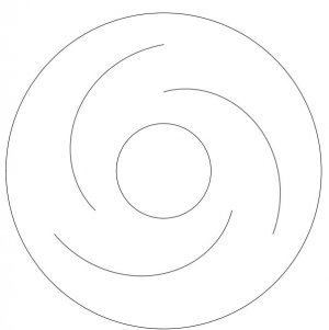
Next open the .dxf file in my CAD program - draftsight. Make three copies of the arc. rotate the second by 120 degrees and the third by 240 degrees. Add cuts for the ID and OD. Giving a file that looks like the below pic. This file canthen be imported back into NcPlot and a gcode file generated to run on the CNC mill.

spiral dxf.JPG
 
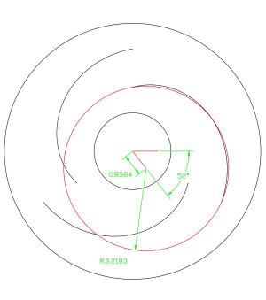
playing with my brain teaser some more, I note a circle very closely approximates the spiral.If there is a professor of mathematics out there maybe there is a relation ship here. I dimensioned the circle for that person.

arc2.JPG
 
It's a cam plate. The path of the arc doesn't matter, as long as it gets from its initial point to its final point. The arcs could be run as straight diagonal lines and it would still work. Look at it in polar coordinates, displacement from center vs rotation is a basic function (r,theta). Tweaking the function would make it steeper, or more progressive, whatever. I assume Hardinge had a reason for choosing the curve they did, with dwell in the middle. The circular approximation you discovered should work great. You probably won't notice any difference at all in the motion.
 
About 20 years ago, I generated an Archimedes spiral through an arc of 720º for a product we were developing for an oncology tool. I did essentially what you have done, increasing the radius by ,1mm per degree of rotation and calculating x and y coordinates. Then I wrote a simple G code routine which was used to cut a slot in each of two steel guide plates with a wire EDM. The plates were used in conjunction with a piece of stainless steel shim stock to create a mold for casting an epoxy composite. The positional accuracy of the slot had to be within .1mm at any location along its length

The process needed refinement as removing the shim was difficult. I found a company that could cut the epoxy directly using a diamond wire saw. The problem was that their software could only accommodate a total of 100 points and my G code program using linear interpolation had 1500 points. My solution was to use arc interpolation and I was able to retain the same degree of accuracy using only 25 points.

This was in the days before we had CAD/CAM and it all had to be calculated out using an Excel spreadsheet. The points used were spaced 30º apart and x and y coordinates were calculated for the start and end points as well as the midpoints on the spiral. The midpoint allowed one to calculate the radius of the arc so there was enough information to generate the G code. Nowadays, it is a simple matter to draw the curve in a parametric CAD program and import the curve into a CAM processor.

Here is a graph of that spiral.
Archimedes spiral.JPG
 
Are you sure that wasn't a Lotus 1 2 3 spreadsheet?
 
I could never afford the 123 spreadsheet. I used As Easy As.
 
Back
Top