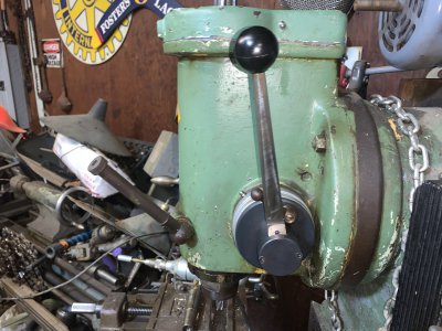
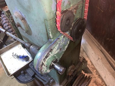
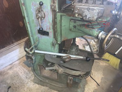
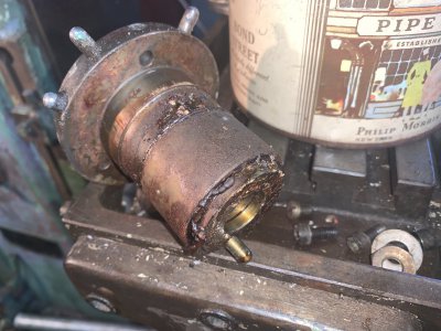
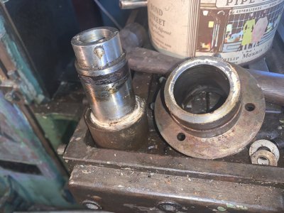
Time to fix up my old Steinel SV4 milling machine.

RaisedByWolves

Mangler of grammar, off my meds.
H-M Supporter Gold Member
Joined
May 7, 2023
Messages
1,332
If anyone needs a manual for this machine you can download it here. Takes it a bit to download so be patient.


What is a Steinel mill?

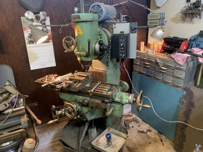
Mine looks like this.


IMG_2390.JPG

This is where it sits as of now. I had to drag it out of its hidey hole to work on it so I figured why not go ahead and chronicle the work Im currently doing on it. Maybe doing so will give me the needed drive to finally get it fully working and fitted out for use.

I got this mill cheap probably 25yrs ago. I've worked on it enough to use it occasionally but its in no shape to do any real fine work with. I havent even been able to oil it for use as, well, Ill get to that in a minute. It has had some strange things done to it in its life, but that is not necessarily a bad thing as the mistakes of others made it inoperable which saved it from wear and is also how I got it so cheap. Its almost like it traveled through time untouched for 40yrs.

IIRC I paid $250 for it.

I believe this was made in the early 70s, possibly earlier and from what I understand it saw limited use in a Tool&Die shop. Its a nice little machine that does not take up much space, but its no where near as versatile as a Bridgeport or other common mills.

So to the the history of this as I understand it and why it has not seen much use by me or anyone for 40yrs. The place I bought it from bought it from the Tool shop to use in their lil mom&pop outfit. Somehow they had the idea that the oil zerks on this machine were actually grease zerks and pumped the whole damn thing full of grease.

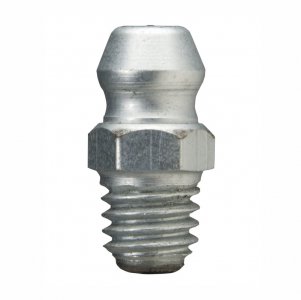
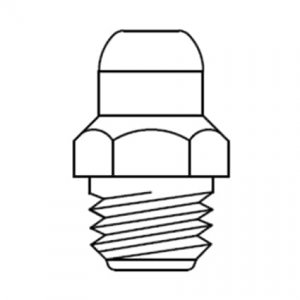
An Oil zerk looks like this.

0901d1968096027d_png_highpreview_800.jpg

Vs a grease fitting


0901d196809601fc_png_highpreview_800.jpg


Main difference is a grease gun fitting wont snap on to an oil zerk.

Given that, they really really had to put some effort into this lubricating venture as the entire damn thing was stuffed so full of grease it wouldn't work anymore. Seriously, I kid you not. It seemed they thought that if greasing it didn't make it work better, than more grease would surely do the trick. They used the old school ropy wheel bearing grease too, not some slippery new age type of lubricant.

Over time the grease they stuffed it with did what grease likes to do and blead all of the oil out of the carrier medium. You may or may not know this, but grease is just oil in a carrier medium that holds it in place. Sometimes the carrier is clay, sometimes its a fancy polimer. In this case I can only figure the carrier in this grease was wood dust.

The entire machine was full of what appeared to be wood that took the form of every nook and cranny. It stopped the gears from turning, the ways from waying and worst of all, broke the gib screws rendering it useless as a milling machine.

I spent the first 3 months of ownership disassembling it and carving all of this oak like dried grease out of the majority of the machine with wood chisels, a small hammer and scribers.

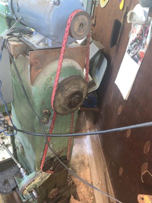
The next thing I did was convert it to a 1hp DC motor and drive which you can see in the pictures. This is actually the 2nd drive Ive had on this as I had my pully ratio way off and trying to mill something in the dead of winter (You seriously have to let this thing warm up in the cold temps) put too much stress on it and it let the smoke out of the driver board.

With the setup as it is now I get variable speeds from 0 to 1000rpms, or higher with the change of a belt and buckets of torque at all speeds.

I hadn't touched this in a longtime as far as fixing it, but then last weekend I stumbled across a lost part for it in a box and I was off to the races. I had bought some Igauging scales for it, but so far only mounted the reader displays as this mill was made before DROs were common so theres no readily available mounting surfaces for them.


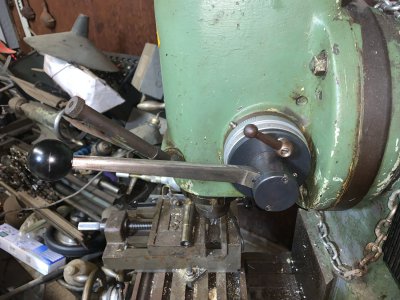
Anyone familiar with this machine may notice the quill handle is not the standard one that came with the machine, but more like the multi position types you can buy for Bridgeport's and such. This machine came with a quill handle that was on a locking taper, so in order to change the handle position you had to loosen the nut, smack the nut with a hammer to break the taper free, reposition the handle and retighten the nut.

Total pain in the ass!

So I made my own multiposition handle and its friggin sweet!

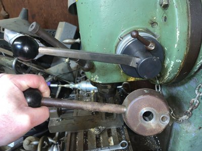
Here it is next to the stock handle. I think they intended lifting battleships or breaking rocks with the standard handle, maybe they had too much metal? Who knows.

The end of the handle where the taper is must weigh 3-4lbs, you could bludgeon an OX with this thing.

IMG_2396.JPG


For those unfamiliar, this handle lets you go from this:


IMG_2394.JPG


To this:


IMG_2395.JPG


On the fly In under one second.

Side note, I probably should have cleaned the lathe before taking these pics. Its sort of a catchall and another totally different long term project in its own right.


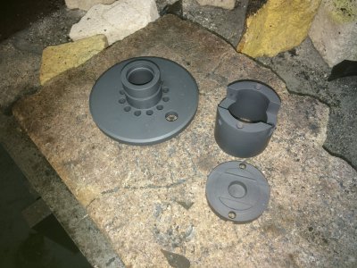
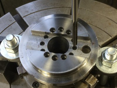
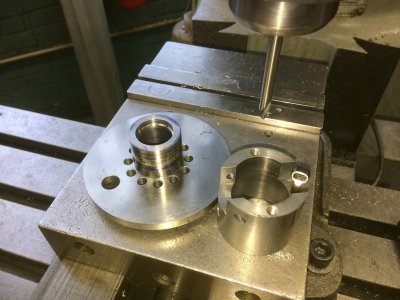
Some pics of the handle parts in the making.

IMG_0687.JPG


Notice the rust? As I mentioned in a different thread, Government work has to wait until there is a slow day, or in this case several slow days over the course of a couple months.



IMG_0687.JPG

IMG_0690.JPG

Finished parts after heat treat.


IMG_0695.JPG


ptlite-icon.svg
 
Last edited:
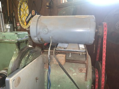
This is the DC motor and motor mount I fabbed up to mount it. It is a Dayton 1hp motor and for the light use this machine will see it has plenty of power. I originally had it "Geared" 1-1 with the input shaft as there is a 1.5-1 reduction in the gears in the head, but this seemed to make the mill sluggish in the cut, so I went to a 3-1 reduction at the pullies and its got much more power now.

I don't think I'm done playing around with the gearing as I would like to get a max speed of at least 1000rpms to facilitate the use of edge finders and such but its only turning about 800rpms right now.


IMG_2407.JPGIMG_2408.JPG


I probably should have wiped the dust off before taking this pic. Our last garage door didn't quite seal and dust blew in every time the wind blew. That has since been remedied and I can now try and have a cleaner shop.

I also initially had no good way of grabbing the spindle nose to undo the collets. This mill takes a Morse #3 collet which is a locking taper and boy do they LOCK! You could easily lock the collet in with an end mill and remove the drawbar and mill to your hearts content without the end mill pulling out.

This causes another problem in that if you accidentally over tighten the collet you play hell hitting the draw bar to get it to release.

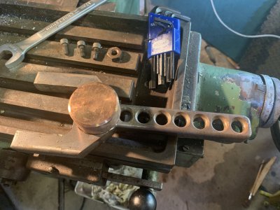
So I killed two birds here and made a custom spindle nose spanner and copper hammer all in one.


IMG_2406.JPG


Onwards and upwards sideways!

Things took a bit of a turn here, and I wound up going down a blind alley.

This machine has a mechanical power feed on the X axis which I disabled long ago while cleaning the grease out and never got around to reattaching.

There is a telescoping drive shaft on the right side that comes from a clutched drive that was inoperable when I got it. This coupled with the fact that you need three hands to get the telescoping shaft back together saw it just hanging loose on the side of the machine.

So the other day as mentioned I found the long lost table lock hiding in a parts bin I haven’t looked in for a long time. Having found that and the lever that goes with it I thought it must be time to reacquaint it with its place on the machine.

The machine is fairly stable without it and that’s saying something given it’s size, but if I’m adding scales and a DRO I might as well make the table locks work, right?

So in fitting that back on I realized I had to pull the saddle out a few inches from its forward most stop to have the handle clear the casting boss for the knee. And while I had that pulled out to replace the lock I was within striking distance of having a chance of putting the power feed drive shaft back together.

So with the wife helping, I applied all the correct foul language( busted the inside of my wrist pretty good) and got that all back together.

Here’s a pic of the power feed drive box on the front of the machine.


IMG_2393 (1).jpeg


Look, a sight glass that is not painted over!!!!:rolleyes:

This is a simple affair with two drive dog clutches that reverse the feed depending on which way you throw the lever.

Except now that it was hooked up and belts added to drive the works I got less that stellar performance when I tried to engage the drive.

It would turn and it looked like it wanted to work, but any resistance to the table or the feed handle and everything would stop.

Soooo, off to my newfound manual to look and see if there is a clutch or shear pin that may need attention.
 
That stripper bolt lock handle for the quill does not look like it would be very comfortable to grip.
 
I have never heard of a Steinel but looking at your pictures I thought it was something European . A very stout looking beast , sounds like it is in good hands . OK funny , back in he mid 80's I used to buy tooling from Teagarden . I got to know him pretty well .
Mark .
 
Ok back to things going sideways.

I tried adjusting the feed clutch and got nowhere. Knowing it was packed full of grease I figured the clutch was just gummed up so I took it all apart.

I had forgot I had cleaned out the innards and left it dry so it’s kinda good that I had to tear it down. It would probably operate fine for the rest of my days with no lube as it’s very overbuilt , but there’s no sense in neglecting it.

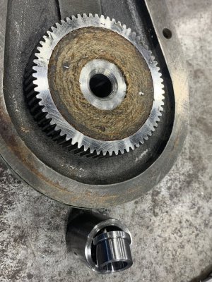
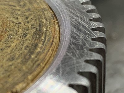
So I got it all apart and cleaned and noticed some wear on the drive clutch.


IMG_2359.jpeg


Nothing terrible, but it looked worn enough that the friction disk had lost some of the original thickness and the aluminum staking pins were making contact with the driven disk so I did some light work to it.

The driven disk measured the same dia as the clutch face so I thought it might be rubbing ob the clutch gear face or interfering with the clutch somehow so I recessed the outer edge of the clutch gear face to eliminate this. I also took a small air pencil grinder and a carbide burr and dished the face of the staking pins.


Just a .020 chamfer.


IMG_2366.jpeg


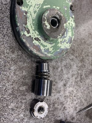
After that I thought about the mechanism that acts on the clutch, just a spring, spring cup, thrust pilot and two adjusting nuts. The fit of the clutch gear in the outer housing support bearing was tight when I removed it and thinking it over, I decided to make it a tight slip fit rather than the light press fit that it was after cleaning. The thought here being the spring may not have enough "Oompf" to slide the clutch gear shaft forward and put pressure on the driven disk.

It initially seemed like this could be a point where it might bind and the spring really isn’t that strong so it only made sense.

So everything was cleaned up, tuned up and ready to go so I laid them all out for a pic to show how basic it all is.

Clutch gear shaft in the outer housing bearing, with parts laid out in order.


IMG_2360.jpeg


Not much too it really and I figured I had it fixed at this point, and I did in a way.

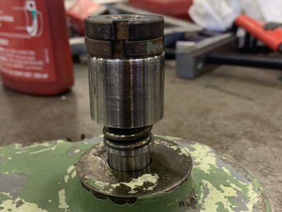
Here are all the parts stacked up in order of assembly.


IMG_2361.jpeg


I got home yesterday and was excited to finish another step in getting this all nailed down and working. I assembled everything knowing it was going to work, flipped the power on and……..


Nothing! No improvement.

It didn’t even work as well as it did before I “fixed” it.

So I took it apart and looked everything over and all seemed well, I even measured clearances again to be sure everything should work and it seemed all right.

Everything was right, it should work!

Took it apart and put it back together 4-5 times trying little tricks and such and got no improvement, in fact it had less and less power the more I monkeyed with it. :unsure:

So I hesitantly decided to try and run it without the back cover and bearing in place to see if I could decipher what was happening.

The springs aren’t on but you get the picture.


IMG_2389.jpeg


I set the drive to its lowest setting in case things got bound up from running unsupported, (Things are only supported on one end by a bushing) turned it on and not a damn thing moved!

Oh wait, I didn’t put the belt and drive pully back on. :rolleyes:

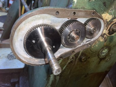
Reinstalled the pulley, slipped the belt on, fired it up and it turned, but less than enthusiastically. I then put my hand on the driveshaft and the whole works, all three gears stopped turning……EUREKA!

There was something wrong upstream from the clutch. So I put it allll back together for one last time and sealed it up with blue RTV.


IMG_2392.jpeg


I then turned my attention to the feed gear change levers and in trying different positions found that the gear it was in was actually neutral! Remember all that hardened grease and how it mysteriously worked less and less effectively the more I played with it?

Yeah.

The residual grease bound it up just enough to make it seem like the gearbox was engaged, but not bound enough to actually transmit power.

Now it works good in some gears and won’t go into others, but I’m sure that is in the change box and hopefully just needs a little attention.

In the gears it does engage I can slow the motor by holding the hand wheel so the clutch is working good and there’s still more adjustment on that left.

I just need to figure out what type of oil to use in this clutch drive.
 
And we have progress!

Dont know why my audio gets messed up filming in my garage. Poltergeists?

O-1 steel with a 1/2" carbide endmill taking a .030 cut.


I think the phone struggles with the EMF coming from the DC drive as this is not the first time I have lost sound and its always while filming a DC drive setup.


Here Im taking a .050 cut, same material and endmill. I don't have the feed right, and this is not the sharpest endmill, but it should be a little bit faster, I just couldn't wait until I get around to working on that side of the machine to figure the speeds out to make some better cuts.


Since the clutch housing covers silicone sealant is cured I filled the gear box with 70wt gear oil. I didn't know how much it was going to take so I filled it to over full and Ill let it settle and find its own level. I ran the oil in while over full to ensure all the bearings got a good oiling since I had cleaned them thoroughly and they were dry. The manual doesnt cover what to use here so I just took my best shot at a happy medium after some reading up on gear oils involving clutches, ie limited slip rear ends.

Now being a gear head machine this thing is noisy. Not enjoying that, I had decided earlier to add a cup oiler to the head vs using the oil gun to shoot a tiny squirt of oil in on the wrong side (in my Opinion) of the gears. This oil cup has a restricted tube for an outlet that drips the oil right on the top of the gear teeth (.050 clearance to top of gear.) for the large driven gear, which then immediately transmits it to the smaller drive gear.

It takes a couple minutes for the cup to fully drain but the oil stays on the gears for a couple days so it doesn't need oiling frequently. Ill simply let it run at its slowest speed while oiling it to let the oil get transmitted around rather than flung off to the side of the case.

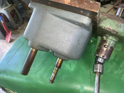
So where does that oil go? Interesting system here. The oil goes from the head down two different drain ports, one leading to the quill and rack, the other to the bevel gears and jack shaft coming from the belt drive on the back of the machine. Basically the power comes from the back via a horizontal jack shaft to a pair of bevel gears, then up to the head gears and to the spindle.

At the juncture of the bevel gears there is an oil well that keeps those gears and the bearings lubricated. When that well overflows the oil then goes to a sump for the fine quill feed gears to lubricate those and their bearings. It is trapped there but can be drained during regular maintenance to keep things from running out and getting messy.

There's also a bearing at the top of the spindle that needs lubed, but you just kind of spill oil on the splined shaft next to the cup in the center of the of the head and it just dribbles down to that bearing.

Lots of fun if you get in a hurry as it will sling the oil right in your face, so I oil that first and let it settle a bit.


IMG_2404[1].JPG


This quieted down the head and bevel gears considerable but you can tell its still a little loud when running.

Now I need to go inside to have a look at the feed drive gears and get that all cleaned up and working. That will involve turning the machine again which at 1200lbs is not easy. If I get it rocking a bit I can get it to turn with some difficulty by myself. The chain (Now removed ;)) was so I could lift it with the cherry picker to move it, but there's too much to move out of the way now to get that in there, so I struggle.

.
Got it spun around a little bit using brute force and ignorance and attended to the feed gear shift levers.


I thought I had these apart years back and If I did I certainly didn't clean them up any. I think I tried but got stymied by the levers being frozen in place (you'll see why in a bit) and probably quit as I didnt have the power feed hooked up anyway.


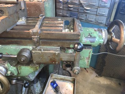
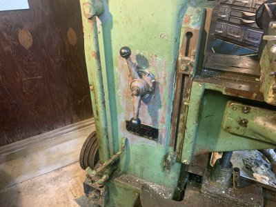
I brushed off 25yrs of dust, dirt and grime off of the area around the change levers before opening it up. Off to the right in this pic you can see the table lock lever and clamping block that got this whole mess started. Its right above the knee handwheel and so close it wouldn't start on the threaded stud without removing the saddle.


IMG_2415.JPG


Once I got the levers freed up and removed I was able to remove the shafts and the casting they mount in and this is what I found.

You guesses it, rock hard grease.


IMG_2416.JPG


That whole brown ring below the key is all grease, no ide what the white powdery junk is.


IMG_2419.JPG


Somehow i neglected to take pics of them all clean and shiny, but just picture all the brown gunk gone and shiny metal in its place.

All back together and working smoothly.


IMG_2423.JPG


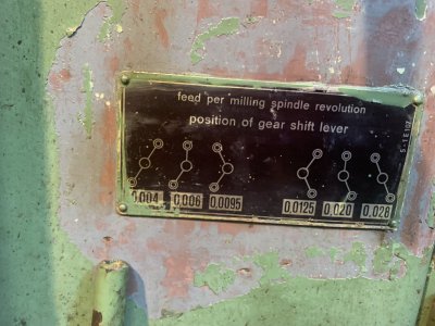
I also rediscovered the gear feed rate chart. Turns out there is no neutral so there may be a problem internally.


IMG_2424.JPG


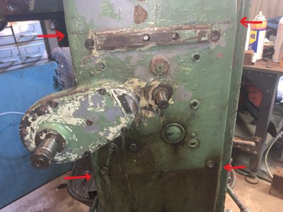
That means Ill be diving into the gear box to see whats up. That is behind this plate, the four outer most cap screw heads outline it. ETA: I added red arrows to make it more clear.


You can also see the sight glass (Painted over and just below and to the right of the feed pully input shaft.) and what Im hoping is a drain screw here if you look close.


IMG_2426.JPG
 
Last edited:
Woke up today thinking I had a thought and as it turned out I shouldn't have thought it.

Looking at the feed gear selection chart last night and realixed this gearbox does have a neutral. Neutral is when the bottom lever is in the center, this thought made me happy as I figured I would just rinse out the gearbox and fill it with fresh gear oil and call it good.

I cleaned the sight glass with acetone and filled the gear box with diesel fuel and ran it in (I thought) every gear to clean things up in there.

Got a nice bubbling action going in there so I knew it was working.


IMG_2429[1].JPG


Kinda hard to see with the flash drowning it out, but there's bubbles on top of the diesel.

I ran it in every gear position for 5 min or so to get things cleaned up but I noticed that the top gear lever didnt seem to cause the speed to change when it shifted. So I realized I would have to go into the gearbox to see whats up.

As soon as I had the box out I saw the problem.


IMG_2432.JPG


OOF, thats fresh too.


IMG_2433.JPG


Not good, not terrible.

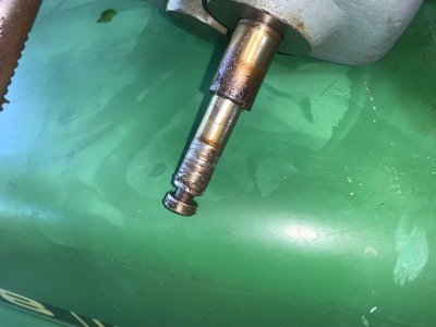
The pin that moves the rear selection shaft broke off at some point and by working it around it caused it to chew into the shaft a bit. Now that I have the gear box out Ill need to remove this shaft and clean it up and figure out how Im going to get the gear change lever out to fix that.


ptlite-icon.svg

IMG_2436.JPG


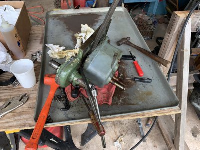
I got the gear box onto a tray and begin to crack it open. I hate splitting gear boxes, its so messy, things you cant see fall out and there's no reference as to where they go and they usually fight you when they have been together for long periods of time. This has been together since the 70s, so it put up quite a fight..


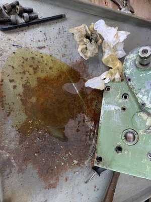
Always put the gear box on a suitable tray for disassemble. No matter how well you think you drained it, there still oil in there waiting to mess up your good sheet of old weather-beaten plywood.


IMG_2557.JPG


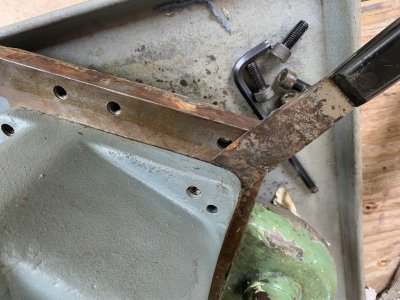
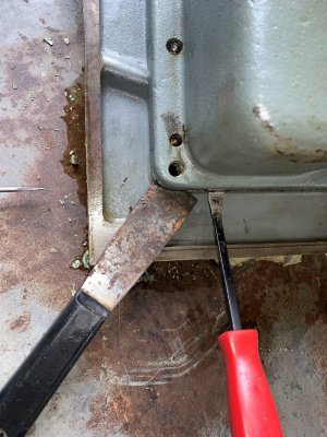
So now that it has leaked the appropriate amount and the gods of spillage have been satisfied its time to split it. I usually try and get a scraper in at the corner of the seam with a second one in the opposite corner and wiggle them to pop things lose. That didnt happen.


IMG_2558.JPG


Being they are flexible, if you pry up on the scraper and tap the housing with a hammer the scraper will act as a spring and you can just tap tap tap your way to success. Not this time, I had to get a little pry bar in there.


IMG_2560.JPG


And that didn't work either, so I had to get some die hooks out.


IMG_2563.JPG


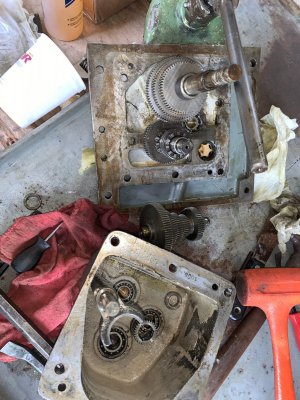
That got it separated enough to see what was what and I saw one of the bearings was stuck on the shaft and pulling out of the housing.

15min of wiggling and swearing and it was apart.


IMG_2564.JPG


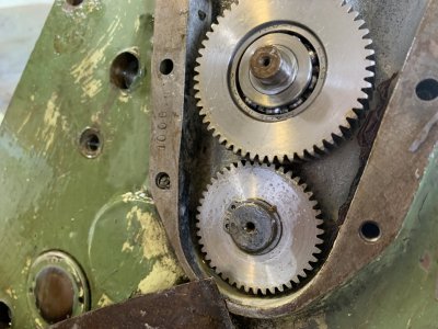
Now in the top of the above pic you can see that buggered up shaft I need to get out with the three gears on it. It must clutch those three gears somehow, but I cant for the life of me work it out and I'm hoping there's nothing more broken in side the gear stack. I Can move the shaft inside the gear stack, but this has no clutch like effect like I'm thinking it should. That shaft gets moved for a reason after all.


Now remember me saying I was done going into the clutch/final drive before? Yeah, this one Jesus clip says different. :rant: It is what's holding the buggered shaft and that gear stack onto this side of the gear box.


ptlite-icon.svg
IMG_2565.JPG


I got that off but had to go eat so Ill get into it more tomorrow.


.
 
Any idea the age of your mill?
Interesting that has an Italian bearing.
I had a smaller Steinel horizontal many years ago which was also quite well made.
 
Any idea the age of your mill?
Interesting that has an Italian bearing.
I had a smaller Steinel horizontal many years ago which was also quite well made.
My serial number is in the low 600s, Im thinking early 70s or so.


With a liberal application of hammers and ther proper shaft drift I got the shaft out. Pretty neat arraignment for the gear change and selector and thankfully there was nothing broken, except for my understanding of just how simple this mechanism works.


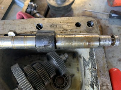
Here is the shaft with the inner shift shaft and sliding key that selects each gear individually.


IMG_2579.JPG


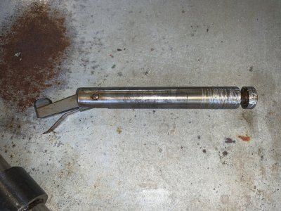
And here is the shift shaft removed and you can see the gear selector key and flat spring.


IMG_2581.JPG

Now how this works is the inner shaft with the key slides inside the shaft the gears rotate on. When the inner shaft is moved it catches the key way of the gear selected and drives the gear via the keyway.


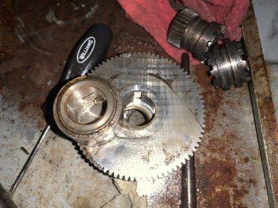
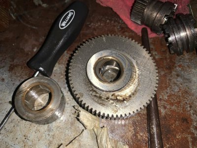
The detent for this is a thick washer between each gear that does not have a keyway cut into it, which the sprung key has to ride up and over to get inside the next gear.

Here you can see one washer on top and another down inside the gears protruding beyond the edge of the hole in the next gear


IMG_2584.JPG
IMG_2585.JPG


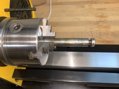
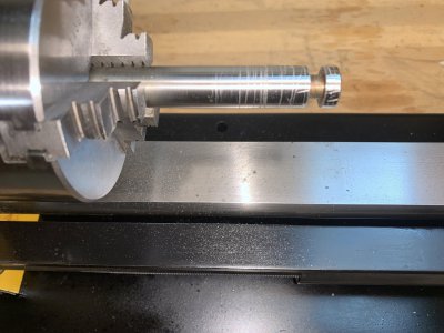
Up next was cleaning up that boogered up shaft and what did I use, My New (to me) Mini lathe!

Chucked it up and hit it with a file first, then hit it with some fine sandpaper and it was all cleaned up and ready to go back in.


IMG_2582.JPG


IMG_2583.JPG


I would never be able to get the scratches out of it without reducing the diameter more than necessary, but as finished it will now slide into the gear spindle nicely.


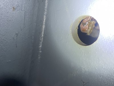
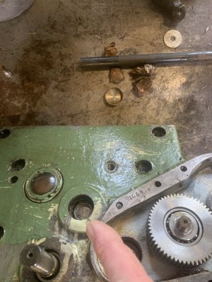
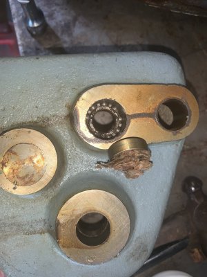
I had noticed some of the gear box bearings were a bit gritchy so I tried to removed then using the oily paper towell trick. All that did was pop the case plugs out the back of the case which made my ass pucker as I thought I broke the back of the case out as it was heavily painted over and I couldnt tell it was even there. But that was OK as it gave me better access to the bearing for removal.

The first one that made me think I broke the back of the case out indicated by my finger.


IMG_2813.JPG


Second one had less of a pucker factor as I knew what would likely happen.


IMG_2815.JPG


Got those and their respective holes all cleaned up and reinserted them with some 680 so they wouldn't leak. The fit was good enough I figured they would be OK without sealant, but I didn't want to risk it.

The bearings were removed and washed in acetone and were fine, just more hard grease. Having seen these were reusable I figured the other bearings that weren't nearly as gritchy were OK too and they just got an acetone rinse in situ and will be greased before everything goes back together.


Now it was time to remove and repair that broken shift pin that chewed up the shaft I had cleaned up earlier.

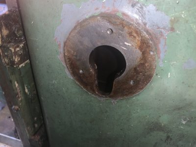
The machine has a keyhole in the side to let the shaft pass out that side which made this step much easier than I thought it was going to be. It actually fought me a bit until I realized it was just another wad of rock hard grease stuck to the shaft that was holding things up.


IMG_2856.JPG


Once the shaft was out I was able to clean it. I found earlier on that a 70-30 mix of diesel and acetone works well as a parts cleaner and strips paint and old hardened grease nicely.

Here you can see the spot on the shaft where the grease was stuck and the 1"x1" greasebooger in the background.

The shaft looks rusty, but everything brown came off with the solvent mixture I made up.


IMG_2858[1].JPG
 
Thanks for sharing!
Good little mills! I had a Steinel horizontal (SH4?), at one time. Gave it to my son. Then upgraded him to a BP.
 
Back
Top