Time to learn about my Teco VFD

JR49

Active User
H-M Supporter Gold Member
Joined
Mar 20, 2014
Messages
440
With the help of you good folks, I hope to learn more about the TECO JNEV-202-H1 (2 HP) that I've been using for a month now. The 220V. single phase input and 3 phase output DIRECTLY to the 1HP original (I think) motor went without a problem, thanks to my reading every post I could find on the subject. My LOGAN 2557VH has variable speed drive, that seems to work perfectly, so I figured out how to set the VFD on 60Hz. and I plan on leaving it there, unless I have problems with the V. drive. I really just planned on using it to convert the current to 3 phase. I've been using it now, by using my long arms to simply reach over and press that tiny run/stop button on the VFD front panel. I have the original FWD/STOP/REV drum switch that I eliminated when connecting the VFD, and wood like to re-use it (with smaller wires of coarse). About my capabilities, I know electircity (house and shop wiring, etc.) its ELECTRONICS that I'm stupid with! For example, I have figured out that the drum switch in basically a on/off/on toggle switch and am sure I can use a continuity tester to know which terminals to hook the 3 wires (are 3 wires correct) to the drum switch. Its the other end of those wires that I'm lost! What terminals to hook them to, on the "control signal terminal block", what to program the VFD, What does NPN and PNP mean (very basic terms please), and which position should those little switches be in? Also, do I hook the wires up THEN program the VFD or program first then hook up wires? I'm not being lazy here, I've read the manual MANY,MANY times, but, unless it says "hook this wire to this screw" I'm lost. Hoping for BASIC instructions, thanks, JR49 PS, Wife read this and said I run-on too much---SORRY (will work on being more brief)
 
More information is better than not enough.

I looked through the manual and it looks like you don't have to do much to set it up to use your old drum switch. The factory default settings don't require any changes except as follows

Set F04, Run command source to 001, External terminal

Set SW1 to NPN (see page 5)

See page 28, NPN, figure 11.1a
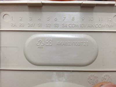
Connect Forward to S1 (terminal 4)
Connect Reverse to S2 (terminal 5)
Connect the common wire to COM (terminal 8)

NPN (sinking) and PNP (sourcing) refers to the direction of electron flow in the circuit. For the purposes of this discussion, if SW1 is set to PNP then you would use 24V (terminal 3) as the common. If SW1 is set to NPN then you would use COM (terminal 8) as the common. Under no condition would you use both the 24V and the COM terminals.
 
I have a TECO on my BenchMaster, but no idea how close it is to your model (I think it's the 1HP rating.) Jim was one of the helpful guys when I was wrapping my mind around setting mine up, so I'll try to pay it forward and take a photo of how I wired it to see if it helps you (just give me 7-8 hours and a reminder if I forget...)

My programming was super-simple - one switch is Fwd/Stop/Rev, one E-Stop and a speed control. It's all this little machine really needs, so I didn't bother to get fancy.

Garden sprinkler wire from Home Despot is a good option for the remote control connections. Much better than what RadioShack had locally.

-Ryan
 
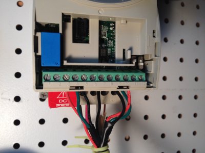
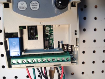
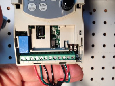
I hope this helps because I can't recall exactly what I did to fully describe it. Maybe this will be a start? You can see I'm set at PNP and V for the switches. My notes for parameters indicate 24V-3, S1-4 (Forward, F11=000), S2-5 (Reverse, F12=001), S4-7 (E-stop, F14=006), speed pot 9-10-11. Sounds like you won't need the speed pot.

These are the choices:
14798610842_d85ed8b2e5_o.jpg
This is how I set mine up (multiple shots to get all the detail...)
14796624524_f44c9d510c_o.jpg14798968245_7bbc810c93_o.jpg14612285240_4d13df1362_k.jpg

-Ryan

14798610842_d85ed8b2e5_o.jpg 14796624524_f44c9d510c_o.jpg 14798968245_7bbc810c93_o.jpg 14612285240_4d13df1362_k.jpg
 
Back
Top