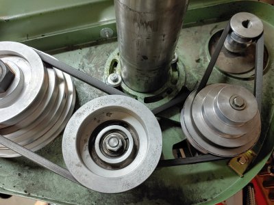
I have a Grizzly 1006 (RF-30 clone) from the early '80's. It is so old it has 2 intermediate pulleys instead of one so changing spindle speeds is even more of a pain than usual. Every time you want to change speeds you have to loosen the motor tension rod screw, pry the motor in against the spring, tighten the screw temporarily, go up top and loosen two bolts and then you can wrestle with the belts to get the combination desired. Then loosen the tension lock, pry out on the motor plate, retighten the tension lock screw and then go back up top and tighten the two bolts for the intermediate pulleys.
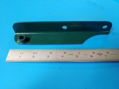
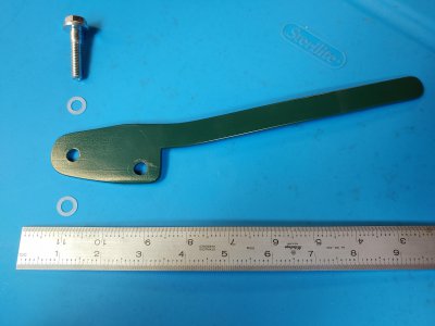
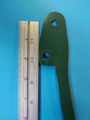
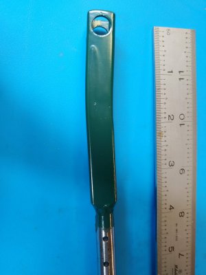
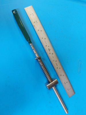
I decided to make a better method for me, anyway. I removed the existing tension rod and spring then I made a bracket and lever to mount to the side of the head. The holes in the lever are positioned such that when it is all the way back the hole for the rod is closer to the head of the mill than the pivot hole is so it over-centers and stays put, kind of like vise-grips. To mount the bracket I reused the existing threaded hole where the tension lock screw had been and drilled and tapped a second hole. I made a bracket to attach to the motor mounting bolts and made a forked rod to go from my new tension lever to the new bracket. The rod has several holes drilled where I can insert a hairpin clip in the right spot so that when the lever is pushed back a fairly strong spring exerts pressure on the motor bracket to tension the belts. I could find a stronger spring if it seems necessary.
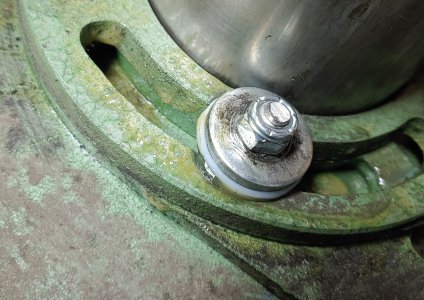
Up top, I removed the two locking bolts for the intermediate pulley carriers and I loctited in two studs instead. I lubed the carriers where they rotate around the column with WD40 Spray Gel Grease liberally and put thick nylon washers and the original steel washers on the studs with nylock nuts. I adjusted the nuts until I could move the pulleys without too much effort but could feel no slop.
Now to change the belts around, all I have to do is pull the lever forward and then tension is released on all (3 on my machine) belts. Move them to the desired grooves and then push the lever to the rear. Done! I have to admit, though, that I will only be a little more likely to bother changing speeds than before. Like my drill press, the current speed is often good enough!
I had another idea for the nuts that clamp the head to the column. What with my DRO and a shelf and wall behind the mill it was getting kind of crowded to get a box-end wrench on the nuts. After making the tensioner, it was impossible without a socket. I ordered a piece of cold-rolled steel hex stock ( I used 7/8" to match the hold-down nuts for my vise). I moved the hand-tighten nut to the bottom, then made two new nuts for the middle and top. The middle one is longer than the bottom one and the top one is longer yet so both are easy to put the wrench on and have a pretty good swing to tighten or loosen without interference. I like it, hope you do too.
Rob
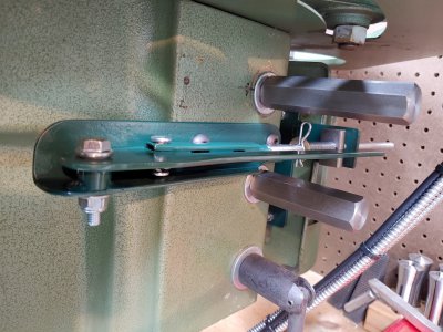
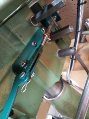
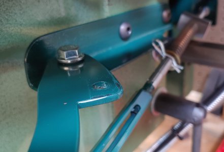
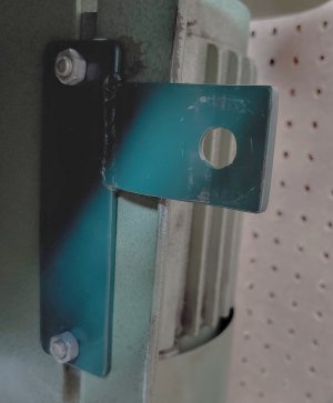
The welded-on piece of the bracket has to be angled out a little to clear the raised edge of the motor plate. I then bent a little curve into it around the hole for the tension rod to give a little pocket for the piece of round stock that pushes on it. I milled a small flat for the spring but it probably doesn't really matter. The hole in the bracket has to be sloppy enough to not grab the rod in any angle it may end up at.
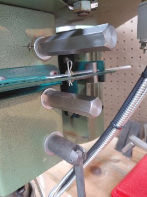
I decided to make a better method for me, anyway. I removed the existing tension rod and spring then I made a bracket and lever to mount to the side of the head. The holes in the lever are positioned such that when it is all the way back the hole for the rod is closer to the head of the mill than the pivot hole is so it over-centers and stays put, kind of like vise-grips. To mount the bracket I reused the existing threaded hole where the tension lock screw had been and drilled and tapped a second hole. I made a bracket to attach to the motor mounting bolts and made a forked rod to go from my new tension lever to the new bracket. The rod has several holes drilled where I can insert a hairpin clip in the right spot so that when the lever is pushed back a fairly strong spring exerts pressure on the motor bracket to tension the belts. I could find a stronger spring if it seems necessary.
Up top, I removed the two locking bolts for the intermediate pulley carriers and I loctited in two studs instead. I lubed the carriers where they rotate around the column with WD40 Spray Gel Grease liberally and put thick nylon washers and the original steel washers on the studs with nylock nuts. I adjusted the nuts until I could move the pulleys without too much effort but could feel no slop.
Now to change the belts around, all I have to do is pull the lever forward and then tension is released on all (3 on my machine) belts. Move them to the desired grooves and then push the lever to the rear. Done! I have to admit, though, that I will only be a little more likely to bother changing speeds than before. Like my drill press, the current speed is often good enough!
I had another idea for the nuts that clamp the head to the column. What with my DRO and a shelf and wall behind the mill it was getting kind of crowded to get a box-end wrench on the nuts. After making the tensioner, it was impossible without a socket. I ordered a piece of cold-rolled steel hex stock ( I used 7/8" to match the hold-down nuts for my vise). I moved the hand-tighten nut to the bottom, then made two new nuts for the middle and top. The middle one is longer than the bottom one and the top one is longer yet so both are easy to put the wrench on and have a pretty good swing to tighten or loosen without interference. I like it, hope you do too.
Rob


The welded-on piece of the bracket has to be angled out a little to clear the raised edge of the motor plate. I then bent a little curve into it around the hole for the tension rod to give a little pocket for the piece of round stock that pushes on it. I milled a small flat for the spring but it probably doesn't really matter. The hole in the bracket has to be sloppy enough to not grab the rod in any angle it may end up at.


