Wiring a 120/240v motor

PNW_Guy

H-M Supporter - Silver Member
Joined
Apr 13, 2023
Messages
201
I just picked up a 90's shaper (wood, not metal) and want to rewire it. It's a 120/240 motor, currently wired for 120v (I'm assuming, as it has a 120v plug). Grizzly put a 14 gage wire on a 1.5hp/20 amp motor, and I'd much rather run it at 10 amps on 240.

The problem is that it's an older model and the wiring diagram in the current manual doesn't color match the motor.

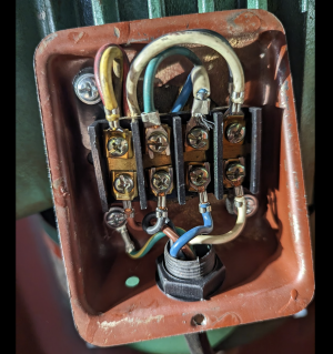
In the photo below, the wires on the bottom are from the switch. The ones on top feed the motor. I have 2 questions:

1) On the top, what position should should I put those wires in for 240v.
2) On the bottom, which two should be hot?
- I have two hots and a ground; there is no neutral in my 20 amp 240v circuit.

More info: it currently has a reversing drum switch that (I'm assuming) has failed. The motor spins up in reverse, but not in forward. In forward, it trips a 20 amp breaker. I have a 30 amp 120/240 volt switch that I'll replace the drum switch with. I do not need reverse on this tool.

Thanks in advance for any info.
 

Attachments

  • motor wiring.png
    motor wiring.png
    2.4 MB · Views: 13
Does the motor have a dataplate or diagram?
It has a data plate, but there's no diagram on it. If there's an additional diagram, the motor will need to be removed from the machine to find it.
 
Nothing on the inside of the terminal cover? Some motors have a little diagram in there
Otherwise, it would be best to ring out the motor wires- got a multimeter?
 
Nothing on the inside of the terminal cover? Some motors have a little diagram in there
Otherwise, it would be best to ring out the motor wires- got a multimeter?
Nothing on the inside of the cover.

I have a meter, but could use some help in knowing what to look for on each wire.
 
Ok, first test the ohms function on your meter, short the probes together and you should get a zero reading or close to
Probes apart should give OL or overrange or 1999 or similar, meters differ
Shut off all AC power to the machine.
Then, disconnect and separate all the motor wires and find the two pairs that each give a steady low ohm reading- the main windings
There will be a third pair that gives a strange reading- different from the other two pairs- that's the start leg
 
Last edited:
Ok, first test the ohms function on your meter, short the probes together and you should get a zero reading or close to
Probes apart should give OL or overrange or 1999 or similar, meters differ
Thanks for the reply. I'm pretty good with a meter, so you don't need to be that basic. I just don't know what readings I should get when testing the wires.

I appreciate the help.
 
Got it- OK main windings should read something like 1.5 to 4 ohms each or thereabouts
Start leg- hard to say. With an analog meter you would see a rising value each time you swap the probes.
Some dvms will do that too, but some go weird and give strange results
Once you have identified the two main pairs that's really all you need
I gotta sign off for tonite but will return tomorrow
 
Last edited:
I'm back, waiting for the mini-eclipse
Well, the eclipse was kind of a dud- too overcast
Here's a diagram: you should only need three positions on the terminal strip
There's a 50/50 chance one of the main windings might have to be swapped to get them phased (won't run right if they're not)
and the start leg can be swapped to invert the rotation if need be
240vmotdiagram.jpeg
 
Last edited:
Thanks for this - I'm out of town, but will pick up my meter as soon as I get home.
 
Back
Top