120v To 240v Help Needed

Damn that magic smoke!! Think I fried the motor(damn again). I turned the motor on expecting to here a pleasant humming, sounded like a cross between buzzing and a grinding, hit the reverse position and the motor did reverse, turned it off, maybe ran for 10 seconds, smelled hot and motor case was hot to the touch, not warm, hot. Thought about this for a minute, removed belt from motor pulley to see if the noise might be bearing but really doubted it. Turned motor on again, maybe 5 seconds and there it was, magic smoke #%*^+!!!

I'm bummed not because I'll probably need a new motor(I'm still extremely happy with lucking into the mill) but because I screwed up the oem motor, I'm kinda sentimental about old machinery.

So take a look and let me know what you think. Live and learn, etc., etc., etc. On the plus side I was thinking of getting a DC motor sometime in the future for variable speed and better torque, looks like the future may be now!

Brian

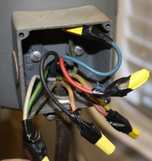
As wired for 120, blue is the hot leg, white is neutral( before I rewired for 240 and before the magic started)
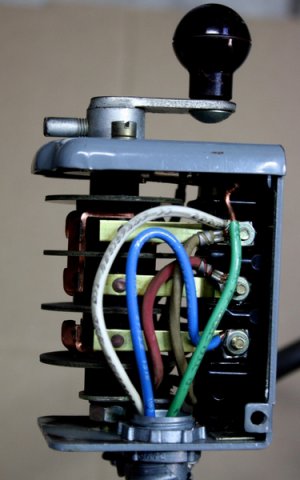
IMG_7292_zpsqb3jjta9.jpg

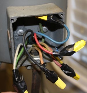
as I wired for 240, the white with the black tape at the bottom is one hot leg, the black hot leg replaced the white neutral, wasn't thinking when I did this(obviously), just replaced the wires where they were before, after the fact I see both hot legs are on the same side so is that the f#*k up?
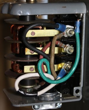


IMG_7317_zpsjfz6hluw.jpg

Should the black leg have gone on this side somewhere(he asks belatedly)?
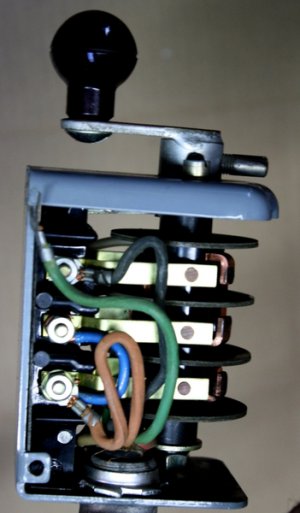
IMG_7293_zpswbbl8hbv.jpg
 
Last edited:
i think there may have been a miscommunication, or misunderstanding........
in post 4,
because i was looking at the last picture of post#3,
the wire combinations i gave were intended to be made at the motor junction box only.:eek 3:
changing the other wires may have been bad.
Remove the motor and if so inclined,
you could try to wire it back up to 115 and see if it runs again before buying another motor, as a suggestion.

3/4 hp- 56 frame- 1725 rpm- motors are plentiful, another motor will not bring the value down
 
...i think there may have been a miscommunication, or misunderstanding........

Its all good, just a another little hiccup in the day, not the first time I didn't fully understand something and moved ahead regardless. So, just for my understanding(and probably others, we're all here to learn, right?) where should the two hot legs have gone?

I will try wiring it back up to 120 and see if its not too fried to run on that voltage, can't hurt at this point. I have a few other motor options in my shop(including a shunt wound DC that came on my other more "experienced" 8530), I'll see what I can come up with. Not worried at all about the mills value, its a long term keeper!


thanks, Brian
 
Last edited:
..I will try wiring it back up to 120 and see if its not too fried to run on that voltage, can't hurt at this point.

Yes indeed!!! Rewired back to 120, it runs super smooth, quiet and cool. Vintage integrity restored, I like that. Not sure how that all works but for now I'm OK with my ignorance, I'm not messing around with it any more, will use as is!!:encourage:

Brian
 
Last edited:
At the risk of getting myself in trouble...

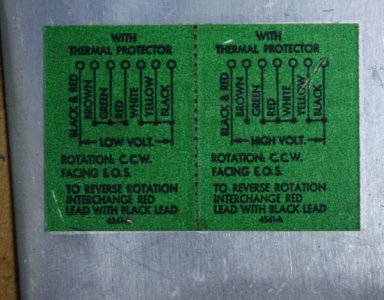
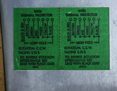
It appears that the BLUE motor wire is what the label shows as BROWN.
So
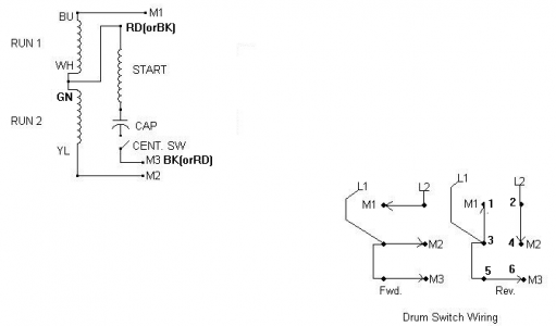
BLUE & WHITE are from one of the two 115v RUN windings
GREEN & YELLOW is the other 115v RUN winding
These must be paralleled for 120: L1+BLUE+GREEN and L2+WHITE+YELLOW 120 volts across both windings.
In series for 240: L1-BLUE, WHITE-GREEN, L2-YELLOW 240 divided between the series. 120 from BLUE to WHITE and 120 from GREEN to YELLOW, 240 total.

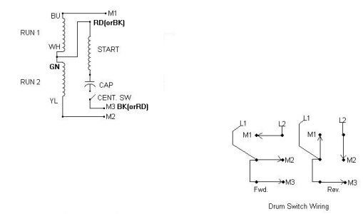
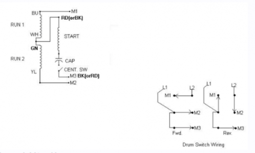
RED and BLACK are the start winding. This winding MUST have 120 volts!! To get that from 240 you simply parallel ONE of the run windings. Meaning one of the start winding connections must go to the junction of the 2 run windings, WHITE-GREEN, always. The other start winding wire is free to be switched to either L1 or L2 as desired for FORWARD or REVERSE, since this also inverts the phase. Here's how I usually wire single phase, cap start motors. I'm not exactly sure how your drum switch works but it looks like it's the same. Your wiring is similar given the blue jumper on your switch. I've changed my drawing slightly to match your motor wire colors. You'll note that since I pick up the motor center voltage IN the motor for the the start winding I only require three wires from the drum switch.
Your thermal interrupt can go in either the M1, M2, L1 or l2 line as you like, where you like. I wouldn't bother however as if it's sized for 120 current the 220 current is only half that and it's not likely to provide any protection, plus it only opens one of the two hot feeds. If you have a decently sized 220 breaker in your feed panel you should be all set.

upload_2015-3-7_23-36-0.png
I hope you find this useful.

Mark

upload_2015-3-7_23-34-52.png
 
Thanks for the great info Mark! As time allows I'll try again with the 240. Does the fact that the motor was hot and smoked for a matter of seconds mean I ruined one of the windings(if thats the correct terminology) or is it still possible that the motor will function on 240? I was wondering about the thermal protector's ability to work with two hot legs, so I see there is no benefit of using it with the 240; my breaker on that circuit is a 20amp.

Brian
 
Last edited:
At the risk of getting myself in trouble...

It appears that the BLUE motor wire is what the label shows as BROWN.
So
BLUE & WHITE are from one of the two 115v RUN windings
GREEN & YELLOW is the other 115v RUN winding
These must be paralleled for 120: L1+BLUE+GREEN and L2+WHITE+YELLOW 120 volts across both windings.
In series for 240: L1-BLUE, WHITE-GREEN, L2-YELLOW 240 divided between the series. 120 from BLUE to WHITE and 120 from GREEN to YELLOW, 240 total.

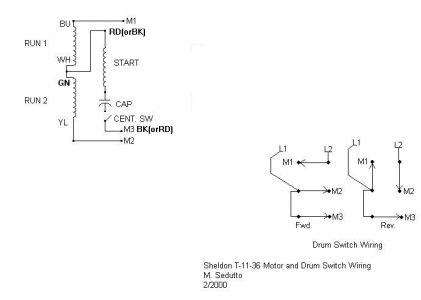
RED and BLACK are the start winding. This winding MUST have 120 volts!! To get that from 240 you simply parallel ONE of the run windings. Meaning one of the start winding connections must go to the junction of the 2 run windings, WHITE-GREEN, always. The other start winding wire is free to be switched to either L1 or L2 as desired for FORWARD or REVERSE, since this also inverts the phase. Here's how I usually wire single phase, cap start motors. I'm not exactly sure how your drum switch works but it looks like it's the same. Your wiring is similar given the blue jumper on your switch. I've changed my drawing slightly to match your motor wire colors. You'll note that since I pick up the motor center voltage IN the motor for the the start winding I only require three wires from the drum switch.
Your thermal interrupt can go in either the M1, M2, L1 or l2 line as you like, where you like. I wouldn't bother however as if it's sized for 120 current the 220 current is only half that and it's not likely to provide any protection, plus it only opens one of the two hot feeds. If you have a decently sized 220 breaker in your feed panel you should be all set.

View attachment 97234
I hope you find this useful.

Mark

30565281-1a00-468d-aaae-a7e2dc6ad4fb_zpsiotx3gja.png

Here's the same pic from above(as I wired for 240) to easier compare the the diagram/info; does this wiring look right? Doesn't look like the high voltage wiring below but I may not be seeing it correctly. thanks, Brian

IMG_7286_zpsgfocgszl.jpg

IMG_731120-20Version202_zpsb4lyytd3.jpg
 
Last edited:
30565281-1a00-468d-aaae-a7e2dc6ad4fb_zpsiotx3gja.png

Here's the same pic from above(as I wired for 240) to easier compare the the diagram/info; does this wiring look right? Doesn't look like the high voltage wiring below but I may not be seeing it correctly. thanks, Brian

IMG_7286_zpsgfocgszl.jpg

IMG_731120-20Version202_zpsb4lyytd3.jpg
 
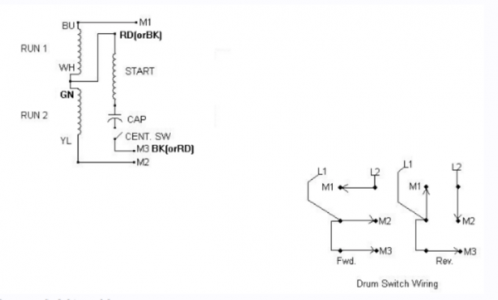
OK, after additional review I'm 99.9% confident in the information I first sent. But I'll clarify that in a point-to-point color list like Ulma Doctor posted earlier. I'll still recommend that you pick up the 110 volts for one side of the start winding in the motor junction rather than using a fourth wire from the switch box. To me that's just a safer way of doing things. It's impossible to put 240 on the start winding this way. Also, nothing should ever be connected to L1 or L2 when the switch is off.


To answer your question, “Did the motor get damaged?”; I can't definitively answer that. I can tell you this: As you re-wired it you had 240 across the start and ONE run winding. Technically the motor SHOULD have turned and run but likely it would NOT have been happy doing so. The fact that the motor remained locked perplexes me but then, I've never done that to a motor. :) The RUN winding could probably tolerate 240 far longer than could the start winding. Bottom line: if you didn't release too much of the magic smoke inside the motor you should be fine. Be alert if the motor starts to run rough or hot. But most (excluding some Chinese junque) motors require a fair amount of overheating before suffering terminal damage and I think you'll be fine. Just an opinion.


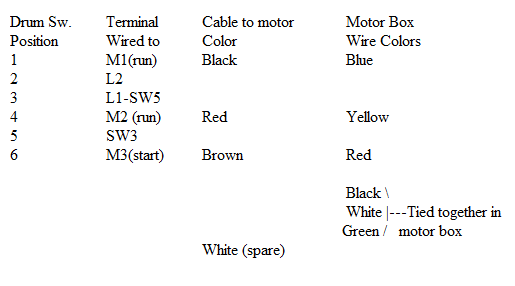
Point to point wiring:

I'll refer to my diagram below for numerated drum switch wiring. Remember to assure all ground conductors are secure.
If motor runs backwards, swap Black for Red at the drum switch.upload_2015-3-9_14-1-54.png

upload_2015-3-9_13-41-43.png
 
Last edited:
Sorry for any formatting issues. Saving tables and images has been less than fruitful for me today. :)
 
Back
Top