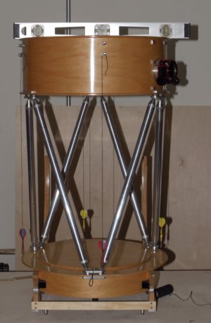
Anyway, how are you planning to attach the secondary to its support? I real of all kinds of methods, and most work, and a few don't! I haven't decided on the spider design. At first I was heading down the wire rabbit hole but may end up doing very much the same as you for rigidity and simplicity.
See #37 in this thread for the vanes and secondary frame.
In my 20" F/4 I spent 2 years fighting 3 different wire spider designs never getting rid of vibrations or collimation issues. Then I gave up and built a 4-vane spider using 0.007,5 galvanized steel (roof flashing; $10 at Home Despot for a lifetime supply). This thing worked so well I never needed anything better. The new 13" F/3 has a similar 4-vane spider (the design shown in the link below (which is just page 1 of this thread). It is strong enough you can grad the whole upper assembly by the secondary frame and pick up the upper assembly forcefully without harming collimation.
Here is a picture of the secondary attachment double sticky taped to the secondary mirror:
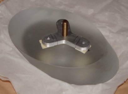
This bracket has:
a) slots cut into it to relieve some of the thermal differences in expansion between AL and Glass
b) kinematic mounting points on the secondary frame to preserve most of the collimation from mounting and dismounting
c) articulates all forces through the CoG of the secondary (see::
https://www.hobby-machinist.com/threads/13-f-3-telescope-build.65805)
d) the secondary lives in a box (like an EP box) while the scope is not being used (for protection of both the secondary and primary)
I used a similar model for my 3.8" secondary of my 20" F/4 that I have used for 20-odd years.
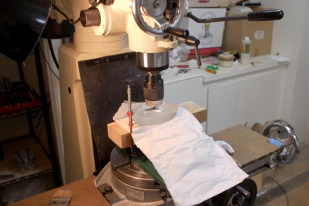
Here is a picture of the secondary sitting on 5 sheets of tissue paper, sitting on a board in the milling vise as the silicone cures. I am using the quill and spindle to hold the secondary bracket square to the secondary as the silicone cures, and using the quill height to set the proper thickness of the silicone blob. Whilecuring I wrapped this whole thing with 5 layers of more tissue paper to prevent crap.....
Regarding the ball ends on your trusses, did you fabricate them or buy knobs from McMaster? Of the latter, are they aluminum?
If I recall correctly, I got them from "cheap balls" 1" 6061 balls with 1/4-20 threaded holes.
All I did was spin them up on the lathe with 1500 grit paper to polish them.
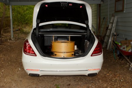
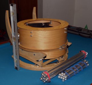
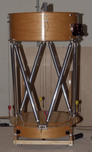
When complete, mine will be a 16" f/4.3 6-truss design. The details of its aesthetics is still up in the air, but will probably end up more functional than artistic. I don't plan on transporting it much and want it stout and not losing collimation too easily.
I am hoping the mechanism I built will hold collimation through disassembly and reassembly!
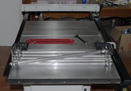
I collimate the scope by changing the length of the poles. The balls were drilled and tapped for 4-40 set screw that holds the 1/4-20 threaded rod (4140) in the ball. The pole end is threaded 1/4-20, and the tube has a 1/4-20 star nut inside.
A 6-pole truss with adjustable pole lengths is known as a "Stewart Platform" and has several important properties:
a) 6 degrees of freedom supported by exactly 6 points (the balls in the ball races.)
b) adjusting pole lengths allows the upper assembly to translate and tip/tilt/droop in 3 dimensions.
b.1) I collimate with a laser by translating the upper assembly so the laser comes back to the secondary where it originally left the secondary.
b.2) this is why the poles all start off the same length (no tip/tilt/droop)
c) once collimated, the pole end is tightened and the ball race clamp is tightened and the scope remains collimated
c.1) while at the same time the truss is converted from pivoting ends to fixed ends (for evenmore stiffness.)
c.2) once tightened all one has to do is put the poles back where they were and it will be "close" probably very close (we shall see.)


