- Joined
- Feb 5, 2015
- Messages
- 662
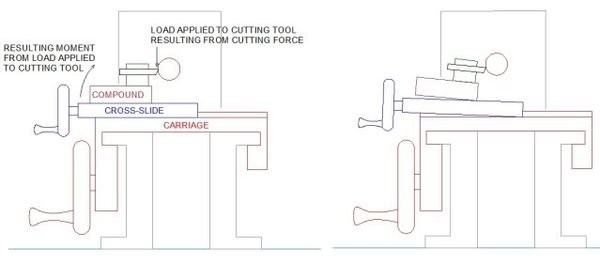
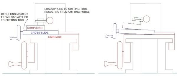
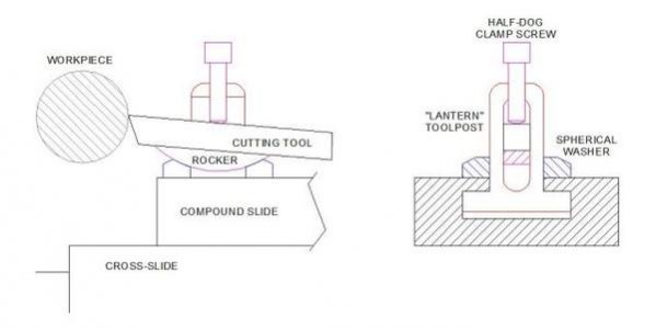
Here's a simple sketch, familiar to most of us, showing the cutting force applied to the tip of a lathe cutting tool and the resulting (exaggerated) "tipping" of the compound, cross-slide and carriage of the lathe. The cutting tool drops below the center line momentarily as the structure flexes and then lifts, depending on speed, feed and setup rigidity, then the tool returns to the normal position. The process becomes repetitive and we have "chatter" which occurs in cut-off situations with small lathes (or during heavy cuts).
Machinists and most hobbyists with a few years experience have a good grasp of this so perhaps the post can be considered as "light entertainment", LOL.
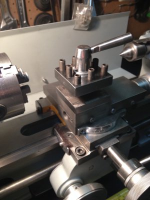
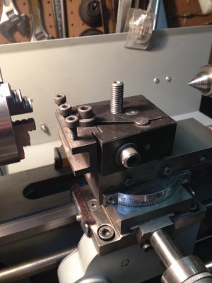
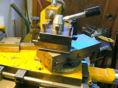
Most small lathes are delivered with four-way toolposts and these can be satisfactory if the dimensions are appropriate to the compound mounting surface. In my experience, most operations required by the compound slide require setting the compound angle between 25 and 45 degrees. But when adjusted in that manner on a small machine, the four-way lacks rigidity because the cutting tool isn't supported against the downward cutting force as can be seen in the following photo. (Incidentally, if the compound is adjusted parallel to the ways as is usually shown in ads for little lathes, it frequently interferes with tailstock operations - if it is perpendicular to the ways, it can interfere with cross-slide operation. Large lathes are unlikely to have these problems of course.)
The tool, mounted in the 4-way toolpost, is cantilevered off the compound mounting surface. When the half-dog screws are tightened to clamp the tool securely, the thinner lower section of the toolholder deflects as a result of the clamping pressure. The tool is not necessarily tighter and NOW the cutting edge has been forced below the spindle centerline - not helpful if one wants to reduce chatter.
A couple of decades ago I tired of the chatter when parting off steel workpieces over an inch or so in diameter. Bad finishes resulted and the parting tool required frequent "touch-ups" at the grinder because of pounding on the tip. Sometimes the tip would chip and all work came to a halt, occasionally catastrophically (to the workpiece). Because the parting operation is usually the last (or near to it) a lot of invested time can be lost !
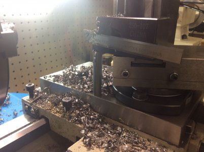
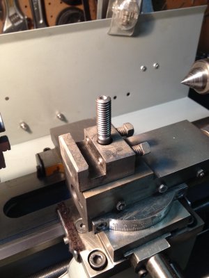
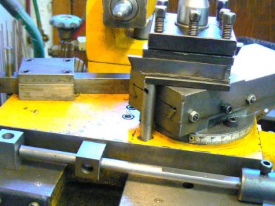
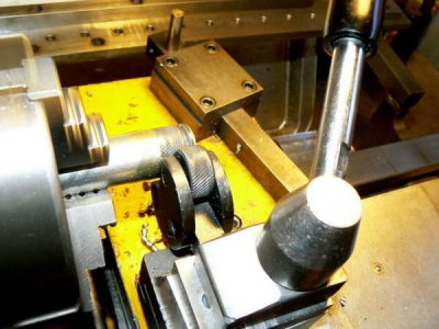
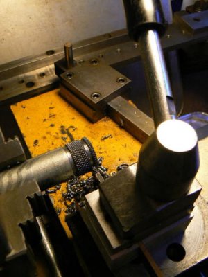
The following was a quick-fix for the problem and it worked well. Tapping a hole in the cross-slide allowed installing a 1/2 diameter steel rod directly under the toolpost. The cutting forces were then transmitted directly to the cross-slide and the carriage. There was no "rocking" and "tipping" of compound or cross-slide as shown in the simple sketch above. The capability of the 8 x 18 lathe when working hard-to-machine materials went up by 100%.
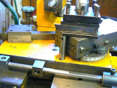
The shortcoming of this "fix" is that movement of the compound is limited, although it's simple enough to unscrew/remove the support rod and restore full compound travel. With the support removed, rigidity is diminished and chatter returns during heavy cuts using the compound.
I looked at the Aloris/Dorian-wanna-be's to see if they might be useful for my requirements but decided not. The tool and tool-holder hang out in space because the size can't be accommodated by the small compound on my machine. The situation would probably be worse than the original four-way toolpost because of the greater leverage at the actual point of the cutting tool.
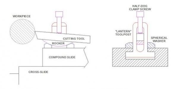
Although many people have little use for Armstrong (lantern) toolposts, I used one for years on an Atlas lathe I once owned. Armstrong toolposts can be very rigid WHEN the forged toolholders - that add cantilevered length - are removed. Most small Armstrong toolposts are proportioned to hold a 3/8 square HSS cutting tool directly on the rocker. A configuration like this is one of the more rigid setups possible. It's clear that there is little cantilevering of the cutting tool once the toolholder has been removed. It's worth noting, however, that the forged toolholders ARE very handy for many light operations. (I'm sketching this from memory so the proportions may not be proper.)
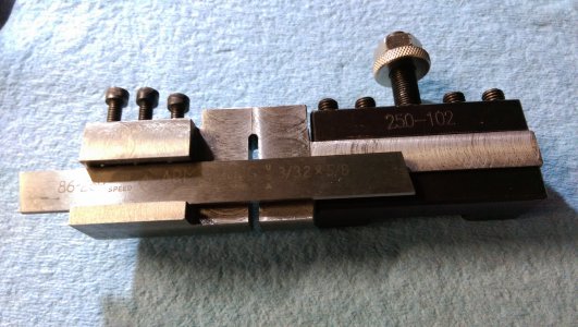
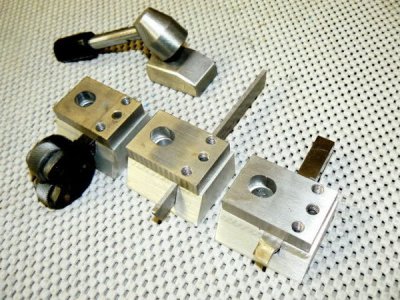
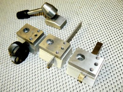
It occurred to me that perhaps a smaller - but more solid - toolholder might be a good idea. I made this small system - it's nothing like a QC design (and is not very quick to change) but it is very rigid. The lower block is dimensioned so that the top surface is exactly at the spindle centerline. Grinding HSS tools without removing material from the upper cutting edge is simple and no tool height adjustment is required - makes the toolholder very sturdy.
The same applies to parting tools and tools of various cross-section dimensions other than the normal 3/8 HSS or brazed-carbide tooling. When machining a blank toolholder, all that's required is replicating the tool cross-section dimensions and allowing the tool to stand proud about a few mils to allow for clamping pressure.
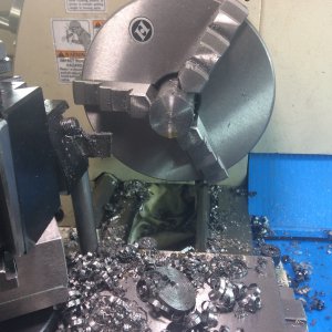
This photo is blurry, the lathe was in operation when I snapped the picture.
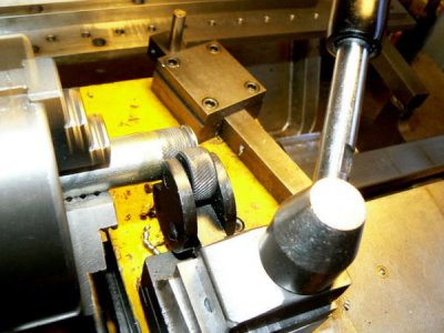
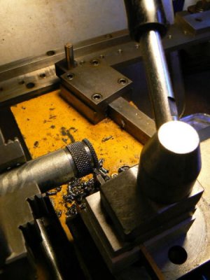
(FWIW, the three holes on the toolholder were intended as angle adjustments for the tool. A socket head cap screw with head diameter turned smooth, was to register in a similar diameter pocket in the compound surface. There were to be three of these pockets machined into the compound with slightly different spacing than those in the toolholder.
By removing the socket head clamping screw and inserting it into a different location in the toolholder, angular adjustment could be varied. When designing the toolholder, I thought this might be useful but I've never implemented the idea. I never got around to machining the registration pockets in the compound slide.)
The little toolholding system works OK on my small Emco lathe; I use it when heavy cutting pressures are expected and frequently when the compound slide is needed. But the four-way toolpost is usually in the lathe - with the support rod underneath the corner of the toolpost. It just seems more convenient, LOL. The four-way can easily support .250 DOC in mild steel with no problem - that's good enough for most HSM applications.
I'm not completely content with either method - QC toolholders are highly addictive and I've used the Aloris system on large lathes in previous workplaces and, in fact, have one on my Sheldon. I designed a scaled-down QC system for small lathes although I doubt that I'll ever make this system - there's just no need for me to produce more than two or three parts at a time. It was more of a mental exercise, I suppose …
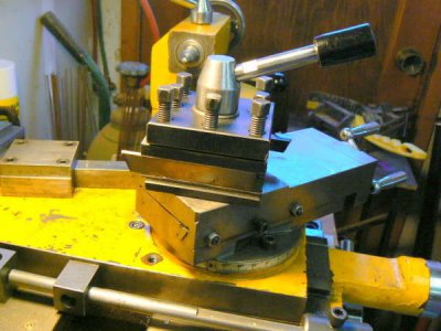
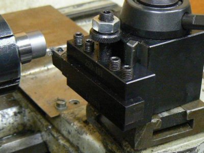
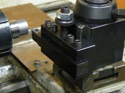
The point of this post is to suggest that a quick change toolpost, mounted to the type of lathe usually found in the HSM shop, might add convenience but often is less rigid than traditional toolholding methods. This is a typical QC system on a larger lathe – the overhang from the support of the compound is apparent:
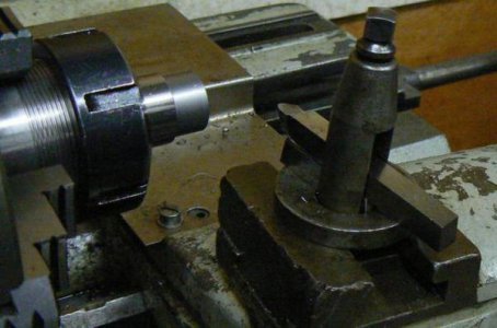
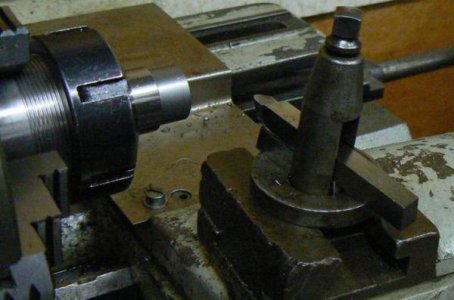
A simple lantern tool post with a 3/8 HSS cutting tool installed. This setup will take heavier depth of cuts than a QC tool holder and is more versatile albeit not as convenient.

Machinists and most hobbyists with a few years experience have a good grasp of this so perhaps the post can be considered as "light entertainment", LOL.
Most small lathes are delivered with four-way toolposts and these can be satisfactory if the dimensions are appropriate to the compound mounting surface. In my experience, most operations required by the compound slide require setting the compound angle between 25 and 45 degrees. But when adjusted in that manner on a small machine, the four-way lacks rigidity because the cutting tool isn't supported against the downward cutting force as can be seen in the following photo. (Incidentally, if the compound is adjusted parallel to the ways as is usually shown in ads for little lathes, it frequently interferes with tailstock operations - if it is perpendicular to the ways, it can interfere with cross-slide operation. Large lathes are unlikely to have these problems of course.)
The tool, mounted in the 4-way toolpost, is cantilevered off the compound mounting surface. When the half-dog screws are tightened to clamp the tool securely, the thinner lower section of the toolholder deflects as a result of the clamping pressure. The tool is not necessarily tighter and NOW the cutting edge has been forced below the spindle centerline - not helpful if one wants to reduce chatter.

A couple of decades ago I tired of the chatter when parting off steel workpieces over an inch or so in diameter. Bad finishes resulted and the parting tool required frequent "touch-ups" at the grinder because of pounding on the tip. Sometimes the tip would chip and all work came to a halt, occasionally catastrophically (to the workpiece). Because the parting operation is usually the last (or near to it) a lot of invested time can be lost !
The following was a quick-fix for the problem and it worked well. Tapping a hole in the cross-slide allowed installing a 1/2 diameter steel rod directly under the toolpost. The cutting forces were then transmitted directly to the cross-slide and the carriage. There was no "rocking" and "tipping" of compound or cross-slide as shown in the simple sketch above. The capability of the 8 x 18 lathe when working hard-to-machine materials went up by 100%.

The shortcoming of this "fix" is that movement of the compound is limited, although it's simple enough to unscrew/remove the support rod and restore full compound travel. With the support removed, rigidity is diminished and chatter returns during heavy cuts using the compound.
I looked at the Aloris/Dorian-wanna-be's to see if they might be useful for my requirements but decided not. The tool and tool-holder hang out in space because the size can't be accommodated by the small compound on my machine. The situation would probably be worse than the original four-way toolpost because of the greater leverage at the actual point of the cutting tool.
Although many people have little use for Armstrong (lantern) toolposts, I used one for years on an Atlas lathe I once owned. Armstrong toolposts can be very rigid WHEN the forged toolholders - that add cantilevered length - are removed. Most small Armstrong toolposts are proportioned to hold a 3/8 square HSS cutting tool directly on the rocker. A configuration like this is one of the more rigid setups possible. It's clear that there is little cantilevering of the cutting tool once the toolholder has been removed. It's worth noting, however, that the forged toolholders ARE very handy for many light operations. (I'm sketching this from memory so the proportions may not be proper.)

It occurred to me that perhaps a smaller - but more solid - toolholder might be a good idea. I made this small system - it's nothing like a QC design (and is not very quick to change) but it is very rigid. The lower block is dimensioned so that the top surface is exactly at the spindle centerline. Grinding HSS tools without removing material from the upper cutting edge is simple and no tool height adjustment is required - makes the toolholder very sturdy.
The same applies to parting tools and tools of various cross-section dimensions other than the normal 3/8 HSS or brazed-carbide tooling. When machining a blank toolholder, all that's required is replicating the tool cross-section dimensions and allowing the tool to stand proud about a few mils to allow for clamping pressure.

This photo is blurry, the lathe was in operation when I snapped the picture.


(FWIW, the three holes on the toolholder were intended as angle adjustments for the tool. A socket head cap screw with head diameter turned smooth, was to register in a similar diameter pocket in the compound surface. There were to be three of these pockets machined into the compound with slightly different spacing than those in the toolholder.
By removing the socket head clamping screw and inserting it into a different location in the toolholder, angular adjustment could be varied. When designing the toolholder, I thought this might be useful but I've never implemented the idea. I never got around to machining the registration pockets in the compound slide.)
The little toolholding system works OK on my small Emco lathe; I use it when heavy cutting pressures are expected and frequently when the compound slide is needed. But the four-way toolpost is usually in the lathe - with the support rod underneath the corner of the toolpost. It just seems more convenient, LOL. The four-way can easily support .250 DOC in mild steel with no problem - that's good enough for most HSM applications.
I'm not completely content with either method - QC toolholders are highly addictive and I've used the Aloris system on large lathes in previous workplaces and, in fact, have one on my Sheldon. I designed a scaled-down QC system for small lathes although I doubt that I'll ever make this system - there's just no need for me to produce more than two or three parts at a time. It was more of a mental exercise, I suppose …
The point of this post is to suggest that a quick change toolpost, mounted to the type of lathe usually found in the HSM shop, might add convenience but often is less rigid than traditional toolholding methods. This is a typical QC system on a larger lathe – the overhang from the support of the compound is apparent:

A simple lantern tool post with a 3/8 HSS cutting tool installed. This setup will take heavier depth of cuts than a QC tool holder and is more versatile albeit not as convenient.


