Accurately measuring and boring holes (28mm)

MrCrankyface

H-M Supporter - Silver Member
Joined
Nov 7, 2019
Messages
434
Good morning!

I've recently tried to up my precision when it comes to lathework but am struggling a bit.

I have a cylinder that is 50mm diameter, I bore it through completely 25mm diameter.
After this I try to lathe a "pocket" that is 8.5mm deep and 27.95mm diameter.

I've tried this twice so far.
First time I used a internal micrometer (5-30mm) and measured it to 27.99 or so but the bearing slid in very easily which makes it seem like the hole is way larger than 28.00mm, hence I can't trust that micrometer?

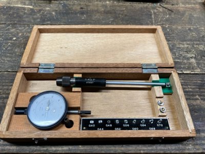
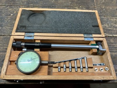
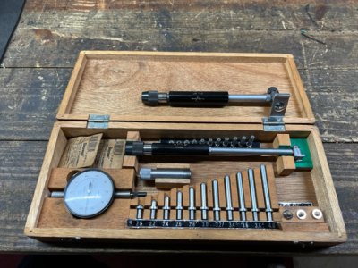
Second time I used a bore gauge and set a external micrometer(that I trust) to 27.95 and got a final measurement of +3 so 27.98 I think? This was a tighter fit but I could still slide the bearing in by hand, which again makes me question if the hole is really <28mm?

It's a bit time consuming so I would appreciate any tips before I spend 3 hours to try again.:grin:

Somewhat related, anyone got a firm grip on fits when it comes to bearings? It's supposed to be 28.00 outer diameter, do I want to aim for a slipfit or press fit? And if pressfit, how do I know which tolerance to look towards?
 
Measuring a bore can be a bit tricky. My preference is telescopic gauges - they do take a bit of practice / technique. Practice measuring some known bore diameters. If your project matters, measure that bore several times, your resulting measurements need to be repeatable. Another approach is to make up some plug gauges, a bit undersize from your target size (the exact size does not matter, so long as you know what that size is). Then you can bore your part to get the plug to fit, then you use the same approach on the target size - with the knowledge of exactly how far you have to go.

Also, make sure your boring bar set up and condition are good - you need to be able to get repeatable results on every pass. Another point, is to learn all you can from the parts made wrong (you know what not to do) - ”do over” corrected by the amount it was off.

I’m not a great fan of the inside micrometer - usually use it as a transfer tool for the measurement to a regular OD micrometer (then the same measuring tool is used for the OD and the ID).
 
The best way to setup a bore gauge is with a "bore gauge setting ring." There are several thousand offerings on eBay, but I'm not sure if there is one to the exact size you're looking for. They vary considerably in price from under $20.00 to close to $100.00.

I've purchased several sets of bore gauges over the years. The most recent are made by Niigata Seiki. They are a bit of a PITA to setup, but extremely accurate. Here are a few pictures of the latest gauges. They cover from .040" (1.0160 mm) to 8" (203.20 mm). I've also included a copy of the manual which includes the setup procedure.
 

Attachments

  • IMG_1417.jpg
    IMG_1417.jpg
    154.8 KB · Views: 24
  • IMG_1419.jpg
    IMG_1419.jpg
    166.9 KB · Views: 24
  • IMG_1421.jpg
    IMG_1421.jpg
    171.6 KB · Views: 24
  • Seiki CDI 50-100-160 Manual.pdf
    170.7 KB · Views: 7
Last edited:
Bearing manufacturers provide tables for determining fits.

Seat of the pants, I would shoot for .0002 to .0005 in. (.005 to .013 mm) press fit on this bearing.
A bottle of Loctite bearing retaining compound is an excellent plan B.
Nice chart but most would have problem.
I used for 6203 ball bear 1.574" OD press fit 0.000,3" to 0.000,5".
If double is size then 0.000,6 to 0.001.

Loctite bearing retaining is a option and Loctite does make one for bearing.
You can do what Chinese use a straight knurling tool inside bore.

I seen this on shafts too.

Dave
 
In addition to the difficulties measuring bores, there can be some complications boring. If your bar sticks out too far it could be flexing. Then, when it reaches a critical point it will 'dig in' and cut unexpectedly over-size. A potential solution is to take several 'spring passes' as you approach your final diameter. Run the bar through a second time without adjusting the infeed (outfeed?!). It'll probably take a small chip. THEN measure. That measurement should more accurately show where your boring bar would be cutting if it were perfectly rigid. Then make your 'final' adjustment and bore. Depending on how much you left to remove in your "final" pass, you may have to make another spring pass to reach your desired diameter, but measure / check fit before doing so.

HTH,

GsT
It is feel and takes time to learn

This what use upto 24" ID for setting bearings.

Note There also the cross slide/boring bar has spring back too. Last few cuts need very small to reduce the spring. The 0.030" you take a 4 cuts and be very careful not take large cut.
The last 2 or 3 cuts you may not to adjust the cross slide.
You use the compound at 11° for a finer feed too.

Dave

20240410_085214.jpg
 
Last edited:
An alternative procedure:
You need a consistently repeatable (not necessarily precisely accurate) outside micrometer to measure the OD of the bearing.
If you have such a micrometer, measure the OD of the bearing. Apply minimal pressure with the micrometer because bearing races are typically very thin and will distort, providing a false (too small) reading. Use that reading as the point of reference to determine your desired bore size.
Then turn a plug gage about .0002" smaller, and with a very smooth finish, than the desired bore diameter and one or more slightly smaller (so you will have some idea when you are approaching finished bore size).
Bore your workpiece and use the plug gage(s) to determine finished size. When the .0002" smaller plug just fits you will have enough size left to polish the bore to a very smooth surface finish.

Edited: bold italic
 
Last edited:
Back
Top