Another Wiring Job

tonlin

Registered
Registered
Joined
Jul 9, 2014
Messages
36
Can anyone guide me in attempting to wire a forward-reverse-neutral switch to an electric motor for a 1938 South Bend "heavy" 9 lathe?

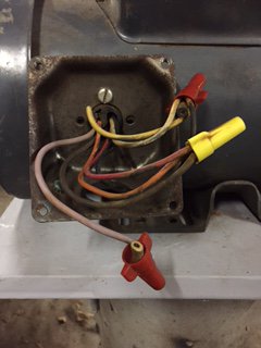
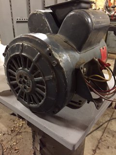
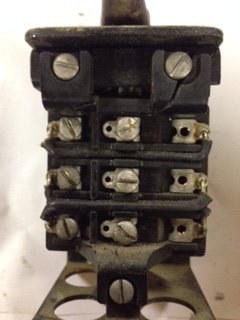
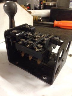
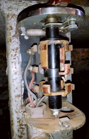
I have included pictures of the motor and switch, however, please note that neither the switch or motor have wiring diagrams (it appears they were removed by a previous owner).


As you can hopefully see in the pictures, the switch is partially broken (if anyone has an extra they can part with, I surely need it). :))


The motor is a reversing 1.5 hp General Electric, single phase, 115/230 volt, 1,725 rpm older unit.


I know nothing about the switch except that it is designed to go "forward, reverse and neutral", I think.

I am ignorant when it comes to electricity so please be elementary with any step by step instruction. :talktogod:

GE 1.5hp electric motor-1.JPGGE 1.5hp electric motor-2.JPGSouth Bend heavy 9 lathe switch-1.JPGSouth Bend heavy 9 lathe switch-3.JPG

Thanks, guys.

GE 1.5hp electric motor-1.JPG GE 1.5hp electric motor-2.JPG South Bend heavy 9 lathe switch-1.JPG South Bend heavy 9 lathe switch-3.JPG
 
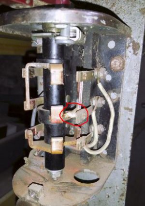
The switch is a drum switch or motor reversing switch. McMaster Carr sells them for about $35 (cat. no. 7065K21). Single phase a.c. motors have a set of start windings and a set of run windings. The run windings are split into two halves, one on each side of the motor. For 110 operation, the windings are wired in parallel, for 200, they are in series. Reversing a single phase a.c. motor is done by reversing the leads of one set of windings. The drum switch does that. The pictures below are of the drum switch on my old Craftsman lathe showing the left and right sides. You may be able to repair your switch. I a brazed a broken contact some forty years ago and it is still going strong. The repair is circled in red.

Switch L.JPG Switch R.JPG

Switch L.JPG Switch R.JPG
 
A picture of the motor data plate and wiring diagram for the switch and motor would be helpful.
 
A picture of the motor data plate and wiring diagram for the switch and motor would be helpful.

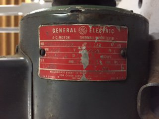
Thanks, Jim, I have attached a picture of the motor plate but as I mentioned in my OP, the switch wiring diagram is missing, so I am flying blind on it.

Appreciate the help, thanks!GE 1.5hp electric motor-4.JPG

GE 1.5hp electric motor-4.JPG
 
The switch is a drum switch or motor reversing switch. McMaster Carr sells them for about $35 (cat. no. 7065K21). Single phase a.c. motors have a set of start windings and a set of run windings. The run windings are split into two halves, one on each side of the motor. For 110 operation, the windings are wired in parallel, for 200, they are in series. Reversing a single phase a.c. motor is done by reversing the leads of one set of windings. The drum switch does that. The pictures below are of the drum switch on my old Craftsman lathe showing the left and right sides. You may be able to repair your switch. I a brazed a broken contact some forty years ago and it is still going strong. The repair is circled in red.

View attachment 94653 View attachment 94654

Thanks, RJ, appreciate your pictures!
 
TJ,

Have you gotten any further help with the motor wiring? If not, I can give a go with you.

Bob
 
TJ,

Have you gotten any further help with the motor wiring? If not, I can give a go with you.

Bob

Thanks kindly, Bob, because I have gotten no further. Definitely could use your help.

Right now, I have the motor and switch with no wiring whatsoever.

I know I have to choose a supply cord of some sort, preferably something that is rated for 115V since my goal is to stay away from 240V for this lathe, if possible. It was wired for 115V originally, I think.

So, if you can guide me on the size of the supply cord, I can pick that up and all I will then need for the project will be (as of yet unknown) individual wire(s) between the switch and motor. Am I correct?

TJ

Hi TJ
Last things first. A 1-1/2 hp motor requires about a kw (750 w/hp) which would mean a draw of about 10 amps @ 110 volts. Depending of the length of cord, AWG 14 should work. For connections between the motor and the switch, it depends on how your lathe was wired. My wiring ran through conduit so solid wire worked fine for it. It is easier to work with than stranded, also easier to come by. For sanity's sake it would be best to have different insulation colors. Green should be reserved for ground and white for the neutral wire. Red and black are usually used for the hot wires. You may be able to buy or beg the needed wires from a local electrician. If you can't come up with the different colors, at least stick with the ground, neutral, hot wiring convention and attach labels to each end of the wire for ease of identification. A paper or tape label protected with a clear heat shrink makes for permanent markers.

A few questions. Does the motor run now? Do you have a multimeter or continuity tester.

Single phase ac motors come in two flavors; capacitor start and capacitor run. They both have two sets of windings, a start winding set and a run winding set. Each set is split into two halves one on either side of the armature. On a capacitor start motor, the start winding is switched off once the motor reaches a certain speed. This is usually done with a centrifugal switch mounted at the back end of the motor. You can identify this motor by the switch plate or, if it runs, by a clicking sound when the motor revs up and when it winds down. The motor doesn't know which way to turn without the start winding. The start winding provides an out of phase current which biases the magnetic field to start in the desired direction. To reverse the direction, the wires of the start winding are interchanged which reverses the phase and the magnetic field bias.. This is what the drum switch does.
A capacitor run motor operates in the same manner with the difference being the start winding is not switched out. This is usually done to develop more torque.

The start windings are usually wired in series and in series with the start capacitor. For a 110/220 motor, the run windings can be wired in series or in parallel. Capacitor run motors may have a series capacitor as well.

The first step in wiring the motor is to identify the type. Most motors have an plate on the back of the motor that provides access to a terminal board. If you remove the plate, you should be able to see if there is a centrifugal switch. If you don't have an access plate, you may have to pull the end cap off the motor to access the internal connections.

Your motor also has two capacitors in the housings mounted on top of the motor. Because of this, I would guess that you have a capacitor run motor. If you remove the covers, you will have access to the wiring. Usually, the capacitors are connected with a screw terminal or a spade connector. I counted six wires coming out of your motor. You would have to have some internal connections to give you the 110/220 and reversing options. I suspect that the capacitors are connected internally so you would have to access those connections in order to identify winding pairs.

[FONT=&amp]This is a lot to digest but it will give you a start anyway. As you progress, we can go into more detail.

Bob
[/FONT]
 
Last edited:
Back
Top