Another Wiring Job

Hi TJ
Last things first. A 1-1/2 hp motor requires about a kw (750 w/hp) which would mean a draw of about 10 amps @ 110 volts. Depending of the length of cord, AWG 14 should work. For connections between the motor and the switch, it depends on how your lathe was wired. My wiring ran through conduit so solid wire worked fine for it. It is easier to work with than stranded, also easier to come by. For sanity's sake it would be best to have different insulation colors. Green should be reserved for ground and white for the neutral wire. Red and black are usually used for the hot wires. You may be able to buy or beg the needed wires from a local electrician. If you can't come up with the different colors, at least stick with the ground, neutral, hot wiring convention and attach labels to each end of the wire for ease of identification. A paper or tape label protected with a clear heat shrink makes for permanent markers.

A few questions. Does the motor run now? Do you have a multimeter or continuity tester.

Single phase ac motors come in two flavors; capacitor start and capacitor run. They both have two sets of windings, a start winding set and a run winding set. Each set is split into two halves one on either side of the armature. On a capacitor start motor, the start winding is switched off once the motor reaches a certain speed. This is usually done with a centrifugal switch mounted at the back end of the motor. You can identify this motor by the switch plate or, if it runs, by a clicking sound when the motor revs up and when it winds down. The motor doesn't know which way to turn without the start winding. The start winding provides an out of phase current which biases the magnetic field to start in the desired direction. To reverse the direction, the wires of the start winding are interchanged which reverses the phase and the magnetic field bias.. This is what the drum switch does.
A capacitor run motor operates in the same manner with the difference being the start winding is not switched out. This is usually done to develop more torque.

The start windings are usually wired in series and in series with the start capacitor. For a 110/220 motor, the run windings can be wired in series or in parallel. Capacitor run motors may have a series capacitor as well.

The first step in wiring the motor is to identify the type. Most motors have an plate on the back of the motor that provides access to a terminal board. If you remove the plate, you should be able to see if there is a centrifugal switch. If you don't have an access plate, you may have to pull the end cap off the motor to access the internal connections.

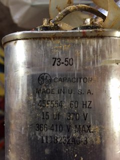
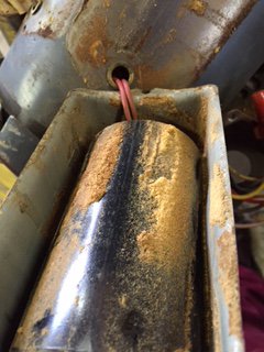
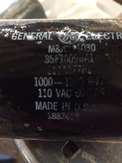
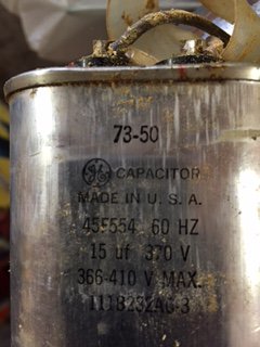
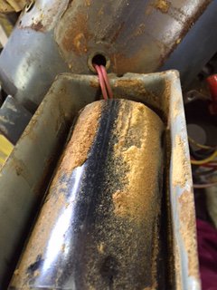
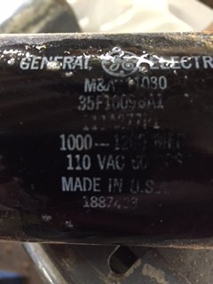
Your motor also has two capacitors in the housings mounted on top of the motor. Because of this, I would guess that you have a capacitor run motor. If you remove the covers, you will have access to the wiring. Usually, the capacitors are connected with a screw terminal or a spade connector. I counted six wires coming out of your motor. You would have to have some internal connections to give you the 110/220 and reversing options. I suspect that the capacitors are connected internally so you would have to access those connections in order to identify winding pairs.

[FONT=&amp]This is a lot to digest but it will give you a start anyway. As you progress, we can go into more detail.

Bob
[/FONT]

Thanks much, Bob. Let me digest some of this, look at my motor's wiring and other items you mentioned, and then get back to you with more questions. Sure appreciate your help!
TJ
 
Thanks much, Bob. Let me digest some of this, look at my motor's wiring and other items you mentioned, and then get back to you with more questions. Sure appreciate your help!
TJ

Ok, Bob, here is what I have found since you gave me some guidance:

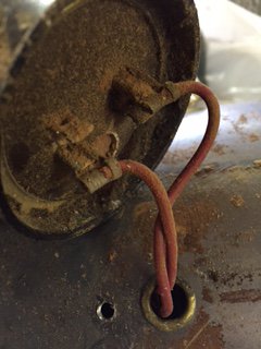
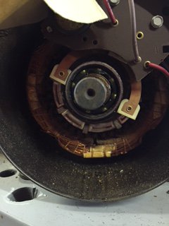
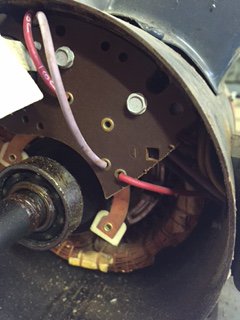
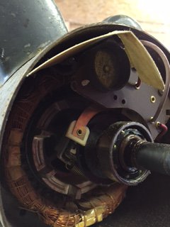
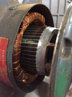
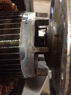
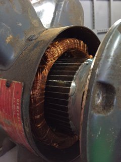
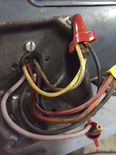
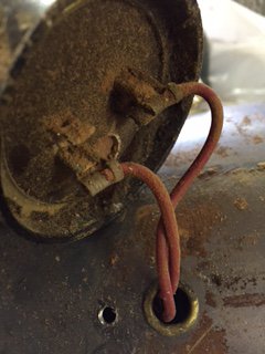
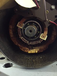
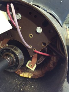
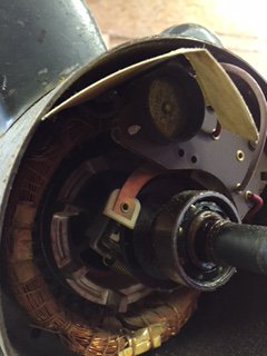
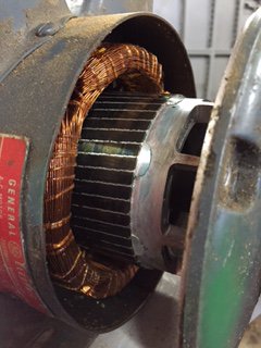
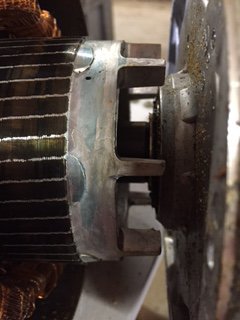
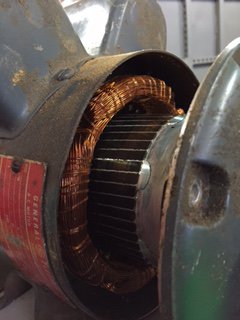
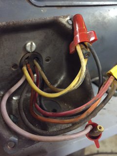
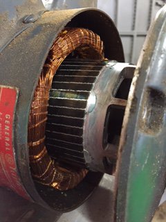
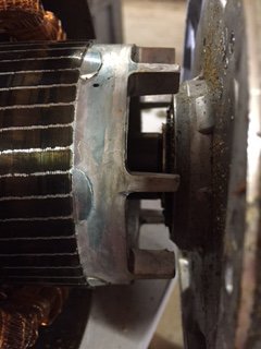
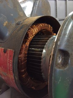
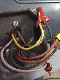
1. I have attached pictures of the capacitors, windings and inside of the back end of the motor. I cannot determine if I have a centrifugal switch or not by looking and don't want to run power to the motor until I am sure I know how to connect properly.
2. Note the motor has seven wires coming out of it instead of six.
3. What gauge wiring should I use between the motor and the switch? (I will run all wiring through conduit).
4. Should I use 10 or 12 gauge wire for the power supply cord since I want it about 10 feet long?
5. I have both a continuity tester and multimeter but hardly know how to use either.

Are the pictures and info enough to determine what I have?

Thanks,
TJ

GE 1.5hp electric motor-7.JPG GE 1.5hp electric motor-8.JPG GE 1.5hp electric motor-9.JPG GE 1.5hp electric motor-10.JPG GE 1.5hp electric motor-11.JPG GE 1.5hp electric motor-12.JPG GE 1.5hp electric motor-13.JPG GE 1.5hp electric motor-14.JPG GE 1.5hp electric motor-15.JPG GE 1.5hp electric motor-16.JPG GE 1.5hp electric motor-17.JPG
 
The easy one first. The National Electrical Code lists 20 amps for 12AWG and 25 amps for 10AWG when sheathed in rubber insulation. Also 10 AWG has a resistance of about 1 ohm/1000 ft. At 20 amps and for a 20' cord, there would be a voltage drop of about .4 volts which is a drop in the bucket at 120volts. 12 AWG wire has a resistance of about 1.5 ohms/1000 ft so the voltage drop would increase to .6 volts, again not significant. From a safety and power loss standpoint, there would not be a problem with 12 AWG wiring both for the line cord and your internal wiring. 10AWG cords are rather cumbersome and it is more difficult to route and make connections.

You have a capacitor start motor. The spring bronze arms on either side of the bearing open the switch when the motor revs up. The wiring connected to the switch contacts is in the start circuit. It is hard to determine anything from the photos of the wiring although it looks like the red wires run to the capacitor. Trace those wires. One should go to a winding and the other to the switch. You need to find the other end of the winding. A multimeter on the resistance scale will show a low value resistance between the winding side of the capacitor and the wire connected to the other end of the winding.

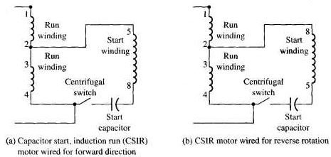
The diagram shows a 120/240 volt capacitor start motor wired for 240 volt operation. For 120 volt, point 1 would be connected to 3 and point 2 would be connected to 4. Point 5 in the forward run position and point 8 in the reverse run position would be connected to point 3. All of those points should be available outside the motor housing.

I would label the wires and note how they are connected now. Then separate them all and try to identify the windings.

There is an alternative way to reverse a motor and that is to connect the switch contact connected to point 4 to point 3 and the start winding point opposite the capacitor (point 5 in the first diagram) to point 4. This also reverses the phase of the current in the start winding, running the motor in reverse.

Clear as mud?

Bob

Capacitor Start Motor 120-240 volt .JPG
 
The easy one first. The National Electrical Code lists 20 amps for 12AWG and 25 amps for 10AWG when sheathed in rubber insulation. Also 10 AWG has a resistance of about 1 ohm/1000 ft. At 20 amps and for a 20' cord, there would be a voltage drop of about .4 volts which is a drop in the bucket at 120volts. 12 AWG wire has a resistance of about 1.5 ohms/1000 ft so the voltage drop would increase to .6 volts, again not significant. From a safety and power loss standpoint, there would not be a problem with 12 AWG wiring both for the line cord and your internal wiring. 10AWG cords are rather cumbersome and it is more difficult to route and make connections.

You have a capacitor start motor. The spring bronze arms on either side of the bearing open the switch when the motor revs up. The wiring connected to the switch contacts is in the start circuit. It is hard to determine anything from the photos of the wiring although it looks like the red wires run to the capacitor. Trace those wires. One should go to a winding and the other to the switch. You need to find the other end of the winding. A multimeter on the resistance scale will show a low value resistance between the winding side of the capacitor and the wire connected to the other end of the winding.

The diagram shows a 120/240 volt capacitor start motor wired for 240 volt operation. For 120 volt, point 1 would be connected to 3 and point 2 would be connected to 4. Point 5 in the forward run position and point 8 in the reverse run position would be connected to point 3. All of those points should be available outside the motor housing. [THIS PARAGRAPH IS CONFUSING TO ME BUT LET ME PONDER IT SOME BEFORE I ASK FOR ANOTHER EXPLANATION AND I DON'T QUITE FOLLOW THE DRAWINGS, BUT GIVE ME A BIT OF TIME ON IT]

I would label the wires and note how they are connected now. Then separate them all and try to identify the windings.

There is an alternative way to reverse a motor and that is to connect the switch contact connected to point 4 to point 3 and the start winding point opposite the capacitor (point 5 in the first diagram) to point 4. This also reverses the phase of the current in the start winding, running the motor in reverse.

Clear as mud? [ I'M PETRIFIED NOW BECAUSE I ACTUALLY UNDERSTAND A LITTLE OF WHAT YOU SAID......] :)

[I WILL WORK ON TRACING DOWN THE WIRES.....]

Bob

View attachment 96394
 
Bob,

Here is some more information if it helps you guess what I have going on with my situation.

My seven wires coming out of the motor are marked as such:

Pink- P1
Black- T5
Brown- P2
Yellow- T2
Orange- T3
Yellow/Black stripe- T4
Red- no markings

Thank you,
TJ
 
Bob,

Here is some more information if it helps you guess what I have going on with my situation.

My seven wires coming out of the motor are marked as such:

Pink- P1
Black- T5
Brown- P2
Yellow- T2
Orange- T3
Yellow/Black stripe- T4
Red- no markings

Thank you,
TJ
TJ,
From what I have seen for other GE motors, the main windings are most likely T1 (red?)-T2 and T3-T4 and the P1-P2 wires probably go to a thermal protector. You need to identify pairs of wires. This is done with the ohmmeter setting on your multimeter. First, note which wires are connected. Then separate all the wires. The intent is to find out which wires correspond to the points in the schematic sent on 2/24.

I have attached a test matrix. Print it out and write in the resistance that you measure between each pair of wires. The boxes with X's can be ignored. When you finish, you should be able to identify the windings in the motor. There should be two pairs with the same resistance value. The thermal protector, if that is what it is, should have a near zero value between its leads. A wire with infinite resistance to all other wires is probably connected to a capacitor and the start winding.

You should also measure resistance from the capacitor leads to each of the wires. and to the centrifugal switch.

It is a tedious job but in lieu of a wiring diagram, about the only way you can safely wire up the motor. If you don't feel up to the task, another way is to take the motor into an electric motor shop and have them work it out. It may cost you a few bucks but it will save your sanity. Once you figure out how to make the motor turn forward and reverse it should be fairly easy to wire up the drum switch and get you making chips instead of connecting wires.

Bob
 

Attachments

  • GE Motor Test Matrix.PDF
    29.1 KB · Views: 11
TJ,
From what I have seen for other GE motors, the main windings are most likely T1 (red?)-T2 and T3-T4 and the P1-P2 wires probably go to a thermal protector. You need to identify pairs of wires. This is done with the ohmmeter setting on your multimeter. First, note which wires are connected. Then separate all the wires. The intent is to find out which wires correspond to the points in the schematic sent on 2/24.

I have attached a test matrix. Print it out and write in the resistance that you measure between each pair of wires. The boxes with X's can be ignored. When you finish, you should be able to identify the windings in the motor. There should be two pairs with the same resistance value. The thermal protector, if that is what it is, should have a near zero value between its leads. A wire with infinite resistance to all other wires is probably connected to a capacitor and the start winding.

You should also measure resistance from the capacitor leads to each of the wires. and to the centrifugal switch.

It is a tedious job but in lieu of a wiring diagram, about the only way you can safely wire up the motor. If you don't feel up to the task, another way is to take the motor into an electric motor shop and have them work it out. It may cost you a few bucks but it will save your sanity. Once you figure out how to make the motor turn forward and reverse it should be fairly easy to wire up the drum switch and get you making chips instead of connecting wires.

Bob

Thanks much, Bob. I will get to work on this and if I can't handle it, I will default to a local motor shop for help. :)
TJ
 
Thanks much, Bob. I will get to work on this and if I can't handle it, I will default to a local motor shop for help. :)
TJ
Hey Bob and others,

After much time spent (wasted?) as well as frustration, I finally faced the fact that my electrical knowledge is too limited and went to a local motor repair shop. Of course, I won't be able to sit down for a month now, but at least this little project is finished so I can move on after I heal up. Thanks for all your effort to help me through this, sure appreciate it!
TJ
 
Back
Top