Anti backlash mod for X2 mill

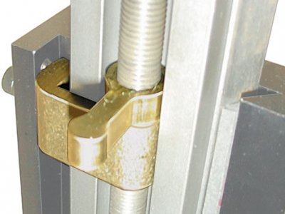
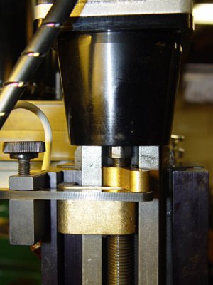
Oh, so when you move the slotted piece back or forth, it turns the nut to take up the backlash. I see now, I think. Does it tighten or loosen against the carriage?

Sent from my VS987 using Tapatalk
Yep, that's how it works. It tightens and loosens against the steel plate that is bolted to the table. If you take a look at your X2 you will immediately see that the plate is required for this to work. BTW the plate is 1/8" thick, seems plenty stiff for this application.

I've found it is fairly easy to adjust. One small refinement I did after the initial install was to replace the philips head screw with an allen cap head -- it's much easier to loosen/tighten. To get a screwdriver on the philips head I had to run the table much further over to the right.

I've got DROs installed on my mill. With the AB mechanism adjusted reasonably tight, pushing/pulling on the table only produces .001" of motion according to the X axis DRO. The mechanical turns dial has to turn .002-.003" before the DRO reading changes by .001". Before the mod I was seeing .005" of table motion and the turns dial had to move .010" before the DRO readout would change by .001".

Aside from removing the table to drill/tap the mounting holes for the steel plate, the most involved part of this project was turning the lead screw nut down so it was perfectly circular. I made an expanding mandrel out of aluminum to fit the ID of the nut, installed it in my lathe (a micromark 7x12) and took it slow, since it was an interrupted cut in steel. I also cut the nut in half (with my parting tool) so I had an extra in case I screwed something up. That also reduced the extent-of-motion penalty imposed by the mod. Even with half the number of threads it's plenty beefy.

The other half of the nut can't be used to mod the Y axis because it uses left hand threads. If I just put a right-handed LS in there I still would have to buy a matching nut, since there must be TWO nuts per axis to implement the mod.

One potential issue is if you have a substantially worn lead screw. Since the two nuts are separated by several inches, it's possible that the outer nut could be in a less-worn portion of the LS, compared to the inside nut. The result would be a variable amount of backlash that depends on the table position. My mill is fairly new so I haven't noticed a problem but YMMV. It could be an excuse to get another lead screw :grin:
 
Seeing the original Sherline adjuster might make things easier to understand. Initially, Sherline was looking for a way to just lock the Z-axis lead screw nut down so they added a lever that threaded onto the lead screw and locked onto the main lead screw nut:

nut lock.jpg

Then someone got the bright idea that if they used a bar to adjust the lever's position they could use the locking lever as a backlash adjuster. They just drilled a hole in the end of the lever handle, added a sliding bar that was lock-downable and voila, an adjustable backlash adjuster thingy.

adjustable2.jpg

I have this device installed on my Sherline Z-axis and it works. On the Z-axis, back lash is not about how much play there is when you turn the hand wheel; its about what happens when the cutter engages the material in a cut. If back lash is excessive, the entire spindle head can move to the degree of that backlash. This results in the end mill/cutter gouging into the work piece. This Z-nut adjuster thing prevents that by tensioning the nut so that the head cannot move much.

As you can see in the second picture, the lever locking knob is loosened and the lever itself is adjusted until backlash is all but eliminated. Then the knob is locked down. The knob and the bar is attached to a separate block that is screwed into the side of the headstock.

Prior to installing this nut adjuster, I would lower the cutter down below the required depth of cut and then back the head up to my desired setting. This took most of the backlash out of the system and the cut would proceed without mishap. After installing the adjuster, I can just dial in my depth of cut and the head does not move and no more crashes have occurred. So, as simple as it is, it works.

What homebrewed seems to have done is to substitute the lever for a pin. As long as you are able to attain enough leverage with the pin to keep the nut in place then this will work. If not, you can add a lever arm and use that to improve it's function.
 
Seeing the original Sherline adjuster might make things easier to understand. Initially, Sherline was looking for a way to just lock the Z-axis lead screw nut down so they added a lever that threaded onto the lead screw and locked onto the main lead screw nut:

View attachment 239091

Then someone got the bright idea that if they used a bar to adjust the lever's position they could use the locking lever as a backlash adjuster. They just drilled a hole in the end of the lever handle, added a sliding bar that was lock-downable and voila, an adjustable backlash adjuster thingy.

View attachment 239092

I have this device installed on my Sherline Z-axis and it works. On the Z-axis, back lash is not about how much play there is when you turn the hand wheel; its about what happens when the cutter engages the material in a cut. If back lash is excessive, the entire spindle head can move to the degree of that backlash. This results in the end mill/cutter gouging into the work piece. This Z-nut adjuster thing prevents that by tensioning the nut so that the head cannot move much.

As you can see in the second picture, the lever locking knob is loosened and the lever itself is adjusted until backlash is all but eliminated. Then the knob is locked down. The knob and the bar is attached to a separate block that is screwed into the side of the headstock.

Prior to installing this nut adjuster, I would lower the cutter down below the required depth of cut and then back the head up to my desired setting. This took most of the backlash out of the system and the cut would proceed without mishap. After installing the adjuster, I can just dial in my depth of cut and the head does not move and no more crashes have occurred. So, as simple as it is, it works.

What homebrewed seems to have done is to substitute the lever for a pin. As long as you are able to attain enough leverage with the pin to keep the nut in place then this will work. If not, you can add a lever arm and use that to improve it's function.

Thanks for the info! I had not looked all that closely at the Z axis on the Sherline -- it's quite a bit different from the table setup. The X2 mill's Z axis drive is completely incompatible with the Sherline design, but the design could work for the X and Y axes (on the other hand, Sherline didn't do it that way for X and Y). The main thing is to arrange things so the backlash can be removed while providing enough leeway to accommodate wear.
 
I've been thinking about how the Sherline Z axis approach could be used on the X2's X axis. It could permit use of a less-modified feed screw nut for the external nut, but would require a slightly different assembly procedure.

In the normal assembly procedure the LS nut is installed into the saddle first, then the LS+table is screwed into it. But, since the external nut's profile has not been altered, it can't rotate on the LS shaft. As a result, it can't be moved into its proper place. It, the lead screw, steel plate and internal LS nut must all be installed into the saddle first (and installed so the backlash can be removed with suitable adjustment). The steel plate would have to have two holes in it so the set screws for the inner LS nut can be accessed.

In this approach the table would be slid onto the saddle in a separate operation, then the gib, bearing block and handwheel installed. As Young Frankenstein said, .....It.....Could.....Work....
 
I know nothing about the X2. Does it not have a split leadscrew nut that allows you to dial out backlash? If not, then maybe you can fabricate one. Of all the ideas that I have seen for backlash elimination on a manual machine, the split leadscrew nut is the best. My Emco lathe has split leadscrew nuts on the cross slide and compound and both can be adjusted to zero - zero - backlash, while turning smooth as silk. Might be a consideration.
 
I know nothing about the X2. Does it not have a split leadscrew nut that allows you to dial out backlash? If not, then maybe you can fabricate one. Of all the ideas that I have seen for backlash elimination on a manual machine, the split leadscrew nut is the best. My Emco lathe has split leadscrew nuts on the cross slide and compound and both can be adjusted to zero - zero - backlash, while turning smooth as silk. Might be a consideration.

The X2 does not have a split leadscrew nut so would need some machine work. My reluctance to go that route is based on comments others have made w/regard to doing a split nut mod on mini-lathes. The nut appears to wear fairly quickly, requiring frequent adjustment. Since the X2 leadscrew nut is buried inside the table it would be a PITA to adjust the nut (you'd have to disassemble the table). This would be particularly unhandy if you have added a DRO, like I have. That's the main reason I was going for something that could be easily adjusted.
 
Oh, okay. It was a thought.
 
Oh, okay. It was a thought.
Well there are a zillion machines out there, who could know the ugly details on all of them, right? As an X2 owner (or a VW owner) I am pretty familiar with the compromises/faults those things have. For instance, the X2 doesn't have tapered gibs :(. I'm happy to get input from other sources because I sure as heck don't know everything, maybe there's yet another approach that is way better. You don't know what you don't know.
 
Back
Top