Atlas milling machine power feed

two of those yoke pieces and the block that goes in the middle are made of steel. The other yoke piece (an original) is pot metal. The steel pieces were made by the previous owner of the mill. If I need a yoke, I will just need to drill that center block and put pins in it to hold it all together. let me know if you need any more photos or dimensions.

Earl
 
Hi Earl and thank you for responding to this thread. I thought I had a found a guy with a parts machine but it it turned out to be a shaper not a milling machine. So I'm back to making my own yoke and shaft assembly. Any dimensions and photo you can provide of the shaft assembly will be helpful. The pictures of the yoke you made will be very helpful and thank you once again for your assisstance.
Best regards , Bill

two of those yoke pieces and the block that goes in the middle are made of steel. The other yoke piece (an original) is pot metal. The steel pieces were made by the previous owner of the mill. If I need a yoke, I will just need to drill that center block and put pins in it to hold it all together. let me know if you need any more photos or dimensions.

Earl
 
I believe I have the shafts and yoke in question. I'll dig through my shop in the next day or two and see if I can find 'em. I'll take measurements and pics when I locate them.
 
Thank you that will be very helpful.

I believe I have the shafts and yoke in question. I'll dig through my shop in the next day or two and see if I can find 'em. I'll take measurements and pics when I locate them.
 
Okay, I did find them. Then I got distracted by machining my QCTP for my little Taig.

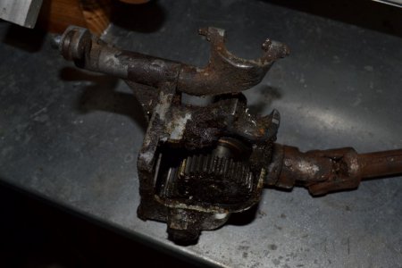
But I did get a whole bunch 'o pictures, and took measurements first. Tell ya what. If you can provide dimensions and pictures of the assembly that goes under the table, I'd greatly appreciate it. Mine is busted, and I got to cast or machine another housing.

Anyway, here's my measurements. Mostly with a caliper, though some with a ruler.

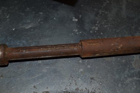
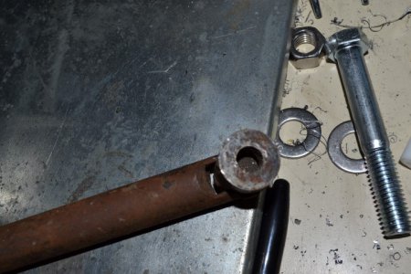
The telescoping part is two round shafts, one nested in the other. A pressed dimple rides in a slot, providing drive.

The big (outermost) shaft :

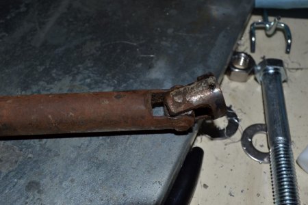
6.25" long, .75" in diameter. The fork is machined into the end of the shaft, and the arms are 1" long.

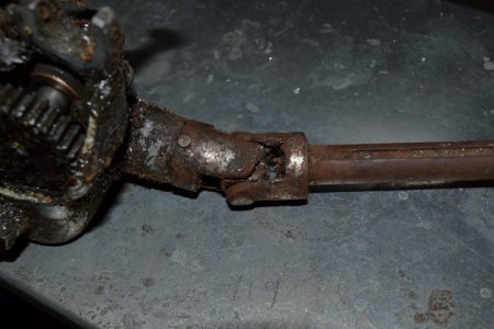
The small shaft is .5" in diameter, 6.25" long (my best guesstimate by shoving a piece of wire down the outer shaft and comparing the exposed vs hidden lengths). The end of the small shaft goes into a U joint half, secured with a pin.

The slot in the small shaft is .125" wide, and can safely go the entire length of the shaft. I'm guesstimating it's .125 deep, based on the "around .125" depth I measured at various points.

The U joints have a .5" cube as the wobbling part,not sure about the pin (it's mushroomed out, and I'm too lazy at the moment to grind it and drive one out to measure).

The U joint on the small shaft is pinned to the shaft. The OD of the joints measures .87", the "base" the arms sprout from is .27" thick, and the arms are .75" long (from the top of the base to the end of the arm). I would surmise they're a tiny bit more than .5" between them, so the U joint works smoothly.

The big part of the shaft has the arms machined into the end of it, if that helps.

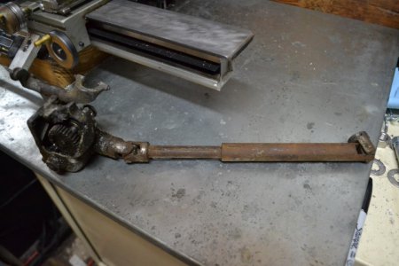
Lastly, the included photos show the phasing of the U joints. Yeah, I know it's a mess. It's broken, and I haven't even bothered with it in 7 years.

Don't be afraid to ask me for more measurements or pictures. It only takes a moment, and I can usually wrangle some shop time when I get home from work.

Here's the tool porn:

DSC_0117.JPG
DSC_0118.JPG
DSC_0119.JPG
DSC_0120.JPG
DSC_0121.JPG
DSC_0122.JPG


Hope it helps, and I would truly appreciate some pictures of the housing (the second picture shows mine is broken). I'd *love* power feed on my MFC, even if it's a DC motor driven jobber.

DSC_0117.JPG DSC_0118.JPG DSC_0119.JPG DSC_0120.JPG DSC_0121.JPG DSC_0122.JPG
 
Thank you for posting the pictures and additional info, it will be very helpful. It will take me a few days to get back to my shop as I am trying to finish up several client projects from my day job. But as soon as I can I will take that housing off and get pictures for you. Feel free to email me directly b.dygger@gmail.com.
Best regards
Bill
 
Hi sorry for the delay in responding, it's always hectic at this time of year. I'm trying to close my office and finally retire, this job is the last hold-out. I will try and get back in my shop and get pictures and measurements as soon as I get caught up.
Best regards and Merry Christmas to all,
Bill

Okay, I did find them. Then I got distracted by machining my QCTP for my little Taig.

But I did get a whole bunch 'o pictures, and took measurements first. Tell ya what. If you can provide dimensions and pictures of the assembly that goes under the table, I'd greatly appreciate it. Mine is busted, and I got to cast or machine another housing.

Anyway, here's my measurements. Mostly with a caliper, though some with a ruler.

The telescoping part is two round shafts, one nested in the other. A pressed dimple rides in a slot, providing drive.

The big (outermost) shaft :

6.25" long, .75" in diameter. The fork is machined into the end of the shaft, and the arms are 1" long.

The small shaft is .5" in diameter, 6.25" long (my best guesstimate by shoving a piece of wire down the outer shaft and comparing the exposed vs hidden lengths). The end of the small shaft goes into a U joint half, secured with a pin.

The slot in the small shaft is .125" wide, and can safely go the entire length of the shaft. I'm guesstimating it's .125 deep, based on the "around .125" depth I measured at various points.

The U joints have a .5" cube as the wobbling part,not sure about the pin (it's mushroomed out, and I'm too lazy at the moment to grind it and drive one out to measure).

The U joint on the small shaft is pinned to the shaft. The OD of the joints measures .87", the "base" the arms sprout from is .27" thick, and the arms are .75" long (from the top of the base to the end of the arm). I would surmise they're a tiny bit more than .5" between them, so the U joint works smoothly.

The big part of the shaft has the arms machined into the end of it, if that helps.

Lastly, the included photos show the phasing of the U joints. Yeah, I know it's a mess. It's broken, and I haven't even bothered with it in 7 years.

Don't be afraid to ask me for more measurements or pictures. It only takes a moment, and I can usually wrangle some shop time when I get home from work.

Here's the tool porn:

View attachment 89014
View attachment 89015
View attachment 89016
View attachment 89017
View attachment 89018
View attachment 89019


Hope it helps, and I would truly appreciate some pictures of the housing (the second picture shows mine is broken). I'd *love* power feed on my MFC, even if it's a DC motor driven jobber.
 
Back
Top