Bridge Crane build

That's a pretty nice looking mill...What mill is that?
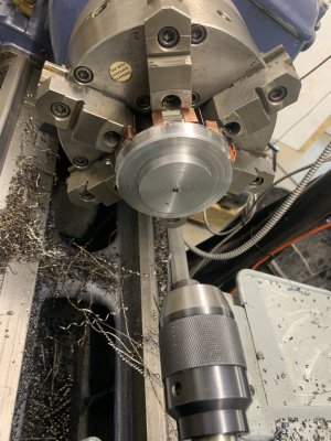
Dan, it is a Grizzly G0757z. It has a 2 speed 3HP rated TENV vertical spindle with a factory VFD. (By amperage it is closer to 2 HP). It also has a 2hp rated single phase motor and a horizontal spindle and the table rotates in the x-y plane.

I’ve used the horizontal spindle maybe twice in the 5 years I’ve had it. I’d spend the money on a bigger table, this one has about 24” of x travel and I could use another 6 inches. The vertical head tilts but no nod, which I have missed on several occasions.

I’d like to add a power drawbar, one shot oiler, and z axis power feed. But those are all wishlist things that may never get done. If I go that far I’ll pull it apart, scrape true, and repaint it too.

I bought this mill, and a Grizzly G0752Z 10x22 lathe as I was approaching retirement, having decided to just dive into machining as a retirement hobby. Had never run a mill or metal lathe before that. I've since sold that lathe to another HM'er, after getting the Monarch 12"CK up and running. Needed the space, as that was before building the new shop. I haven't completely replaced the sold lathe as the 1944 12"CK (14x30 swing) doesn't spin up beyond 1000rpm so it can be a bit slow for making smaller parts, nor will it do metric. I have a 10EE lathe that got sidetracked by the new building that should fill the small end gap, and at some point an ELS would allow metric. The monster lathe (Monarch 612, 25"x50") spins up to 1500 rpm so that gets me higher speeds, but feels like using a sledgehammer to drive tacks using it for small work. And it needs a DRO.
 
Last edited:
OK, looks like a nice mill. Lots of features in one unit. With most things there are compromises. I was really looking for a bridgeport with the rotating X-Y table feature. For cutting things like tapers that could be really handy! Alas, the machine I ended up doesn't have that.
 
Gnashing at the bit, ready to get back to the shop. Have to wait until tomorrow. Mostly picking up pieces from a few mistakes in the shop before I left town last week. At least I got the mill back to running before I left.

I was working on both the bridge end-truck body, and the bearing retainer blocks. I need to cut the 2.5" dia holes in the end-trucks. I was hoping to do that on the rotary table, but realized neither of my mills has the needed 24" of y depth, spindle to column, to rotate the end-truck plates 360 degrees. So I'll need another approach. I could bore out with a boring head, which would be tedious since I'd be working up from a 1" or maybe 1.5" drilled hole. (Total of 8 holes, I could stack them and do 2 or 4 at a time). Or I could build a single point annular cutter (milling trepanning tool?) to run in the mill. TBD ...

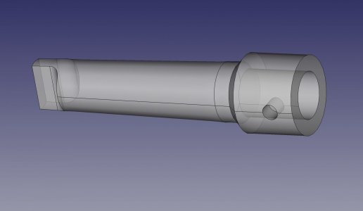
On the bearing blocks, these need to get a stepped center hole for a bearing in grease seals. I started to pilot drill the center. Plan was to start with about 1/4" and then jump to 1" drill, then bore up from there. Well the 1/4" drill snapped off. Was a new, cheap dewalt drill bit, actually fractured lengthwise along one web. (I was pecking with plenty of cutting oil). I was just grabbing an off drill bit rather than one of my better "to size" bits. So now there is a drill fragment embedded in there. I could use a carbide endmill to clean it out. But am thinking I'll make a morse taper 3 holder for the typical 3/4" shank on common annular cutters. Would be a useful thing for the lathe. Wouldn't have a way to harden it but it should hold up for occasional use.
IMG_5058.JPGmt3-annular-cutter-holder.jpg
 
If you would rather buy one . . .
Thanks for the tip. I need the practice so I'll go ahead and make one, only because I have steel in stock. If I had to buy material it wouldn't make sense, but I can finally get out in the shop tomorrow so I'm ready to make some chips.
 
Just plodding along. If I try to rush, I just mess things up.

The recent news of significant structural failures (Oceangate, Carowinds) is a good reminder of why these things need careful thought. I'll have to think what my regular inspection plan is going to be for this crane. Probably annually, as this is not going to be heavily used. These end trucks will need to be a focus of maintenance and inspection.

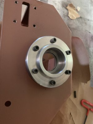
Got one end-truck body welded up and primed, and two bearing plates made. (Scroll back through the posts if you're looking for the axle, bearing and seal design). Since this is the first of two trucks, with 4 axles total, I'm working all the way through one axle first. If that comes out well then I'll try to turn out the next 6 bearing plates and 3 axles in more of an mass production fashion. Yeah, 6 capscrews on this is a bit of an overkill, since they're not really structural.

IMG_5069.JPG

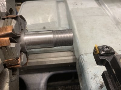
I'm using 41L40 for the axle. Didn't even realize a leaded chromoly was available, started looking for straight 41xx on McMaster and found this. Doesn't machine as easily as 12L14 but it is nicer than any 41xx or 10xx, and with a 85,000 PSI yield strength is suitable for this. This is cutting the 0.969-32 thread on one end for the bearing retaining nut.

IMG_5068.JPG
 
Last edited:
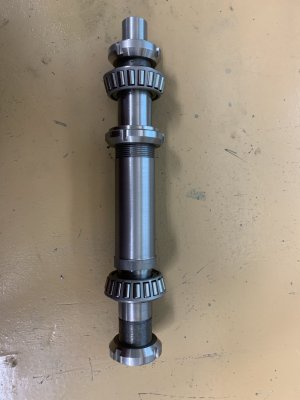
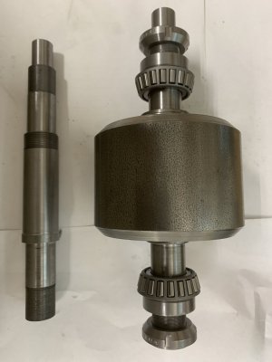
Well these axles are pretty close to my skill limits on machining accuracy. Of course that's how we build new/better skills. Two bearings, three threaded areas, and a close-fit for the central roller per axle. 4 axles total. And a couple bushings between the bearings and outer bearing nuts. Here's a couple shots of the first two axles in various stages of assembly. Will fit one up into the truck (first pic in previous post) before making the last two.
IMG_5070.JPGIMG_5076.JPG
Still need to mill some keyways in them.

The central roller is ridiculously massive at 4.25 dia x 3.0 length. Scale in CAD is not always quite meaningful. Not worth re-designing unless I build another crane. (very unlikely). The CRS is round to within a couple thousandths as tested by a DTI, so I didn't skim the perimeter. Was hoping that would work out as the price increment gets pretty steep for larger diameter stock, and my design called for 4.25. Of course if I skimmed them all to 4.230 it wouldn't really matter. Might make a mandrel when I've got all 4 rollers done and yet do that. Have to see what else the test-fit into the end trucks reveals.

@Dabbler will remember we discussed a v'd roller over angle iron. I'm only doing that on one side, not this initial one. Concerned that I'll get the V's not exactly straight and thus two would bind.
 
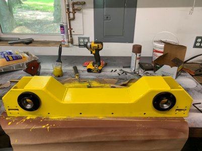
Wasn't up to firing up any of the real machines today, so did some painting - got one of the end-trucks painted. I won't claim to be more than a hobby machinist at best, but a painter I ain't. Period.

Axles and rollers in my previous post sit in the black mounting plates.

Paint is still pretty soft, it'll need a week or so to really harden before handling this. Didn't really mean to duplicate Dewalts color scheme, just wanted a hi-vis yellow for the moving parts. The static parts are white, as is the ceiling. The bridge beam will be this same yellow.
IMG_5084S.jpg

This is one of two. Second one is still pending. Also need to make up the 4 retaining strips (2 per end truck), and probably go ahead and make up the 8 bumper bearing assemblies. I'll also need to drill the 4 holes in the top of this that will hold the bridge down. And make up a nut plate

This design is complicated by wanting top-running trucks and maximizing the clearance under the side rails. So lots of parts go into this. But I'm relatively happy I did it this way. The black bearing plates have an inner shoulder that sits inside the yellow truck. So the vertical load is carried on that shoulder. And the axle and taper bearings will help seat the bearing plates.
 
Last edited:
Back
Top