Bridge Crane build

angle grinders are evil, I treat them as if they're trying to kill me even before I switch them on!
 
where I used to work any time a wire wheel was used it was required to ware, leather apron, usually a welders jacket, goggles and a face shield.
The wires from those wheels are tiny missiles that penetrate everything.
 
where I used to work any time a wire wheel was used it was required to ware, leather apron, usually a welders jacket, goggles and a face shield.
The wires from those wheels are tiny missiles that penetrate everything.
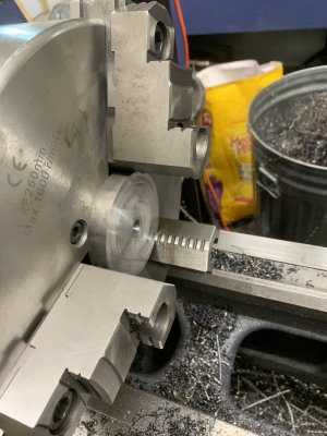
I was using this wire wheel/cup. The deceptive and thus dangerous thing is even at 6000 RPM (rated for 9000), the cup opens out, expanding the diameter, although when spinning it's not clear by how much until you are in contact with the grinding surface. I should have stopped and rethought everything as soon as I noticed that. I was instead caught up in the paddle switch on the new grinder. I'm accustom and prefer the side-mounted slide switches but those seem to have been eliminated, probably as a liability issue.

Like a lot of accidents there is a chain of events that leads to the problem. This one included both a brand new grinder, a brand new wire wheel, unfamiliar behaviour from both, and a failure to stop and re-assess rather than just bowling through.
 
where I used to work any time a wire wheel was used it was required to ware, leather apron, usually a welders jacket, goggles and a face shield.
The wires from those wheels are tiny missiles that penetrate everything.
Don't forget ear/hearing protection.

My father had plenty of horror stories of working the ER and pulling those wires out of people's eyeballs. Dinner conversation as a kid was ... intense. The cupped shaped wheels with twisted/knotted wires are incrementally better at not shooting them as far/hard, so I prefer them. But still dangerous.
 
Last edited:
You'd think I would have had enough of medical issues after last week that I'd be more careful.
New angle grinder, with a new wire cup. Lots of little things, but things went south. Wire wheel sucked in my shirt, yanked the wheel instantly into my gut, stopped and tried to spin again. I sat there struggling to hold the damn thing away from me while the motor burned up.


I'll be adding a shop apron to my PPE for future angle grinder work.
Be careful out there
Just curious, did you get "the look" from your better half? Sometimes that can be worse than the injury, ask me how I know! ;)

Bruce
 
Just curious, did you get "the look" from your better half? Sometimes that can be worse than the injury, ask me how I know! ;)

Bruce
I've sutured her up a couple times. And I've had to deal with the dirty looks from other people when she gets a black eye from the horses. We had a mare that was nearly blind, so that she would startle when you walked close to her. Horse skull to the face is not pretty, she's had some nasty black eyes. Wife is very tender hearted and kept that mare past "safe". (Finally put that mare down this spring). But she knows it is a two way street and isn't going to cast stones.

She fusses and worries, but no "look". Believe me after what I've put her through being hospitalized last week and a few months before, I have absolutely no desire to add to her stress. It has worn on her.

She's always eager to help and more than happy to just "be on hand" if I need a safety spotter. Can't ask for more.
 
Last edited:
Simple things in small bites. Trying to make the side bumper bearings. Two identical blocks just flipped 180. I wanted the blocks to clamp the axlr against the frame without specific bolts in the axle. The axle is offset into the frame to give additional clearance between the outer rim of the bearing, and the 3/8” plate it extends through. The flat face on the axle sits a few thou proud of the block to be assured of actual lock pressure between the axle and frame.
15A81F7B-6726-4A68-B319-D6D9C6B73034.jpeg

I’ve got to cut 8 of these. The upper and lower flat needs to be planar, not clocked off, since both flats contact the same plane of plate on the body. That ruled out using a collet. I want the shaft proud of the block by 4-5thou. Theblock is reamed to a .751 hole. Axle is 3/4 precion ground rod.

DB14F7A2-D097-4FAA-84B3-D16286CC55F5.jpeg
F1752E65-B86E-458D-AF23-9F8AEB2F9BBC.jpeg
There is +/- 3/16th’s movement on the bearing. That’s intentional to get good beam tracking, I’ll add washer/shims to adjust the bearing height.

Need to order some 1/4-20 x 1 1/4 UNC screws, these are a bit l0ng. You can see a bit of the bearing coming through the upper wall in the lst picture.

Made this little clamp fixture to mill the flats That way both flats are parallel. Fixture is just a scrap piece with a hole drilled and reamed, and slit to that hole with a bandsaw.
09D97567-CA22-44B4-9A14-C8B93CF3C0A0.jpeg
 
Last edited:
Ok, that last picture/comment on the fixture wasn't completely clear. This picture should help. Closing the vice tightens down the slit in the fixture.
IMG_5141.JPG


Trivially, here's what the part looks like after milling (before deburring). This offsets the bearing a little closer in to the side, so it protrudes through the other side of the truck body more.
IMG_5142.JPG

I thought about using a collet chuck block in the mill to hold these. Two problems, that would require a flipping the part, and make it challenging to line up the flats. Second problem, I don't have a collet chuck block for the mill. If not for the first issue it would have been a good excuse to buy one!

I did use the collet chuck on the lathe to chamfer the ends though ;)
Was a bit redundant to chamfer it in the collet chuck, as I had to deburr one end with a file to get it into the collet.
IMG_5139.JPG
 
I enjoy the process of designing something, the building it. The axles/rollers on the bridge crane trucks had me stumped for a bit.

This got rather complicated. I'm sure there is a simpler way to accomplish this, just not sure what it is. Well, I know a couple of things I'd do different. I used grease seals on either side of each bearing. A bushing with a couple of o-rings would have done just as well. These aren't going to spin fast, nor does losing a little grease matter, more just keeping dust out of the bearings.

If you look at this picture (repeated from earlier), I had a huge roller.
IMG_5075.JPG
An massive overkill, but that wasn't enough reason to do anything different. Until I thought about assembly. I had originally thought of pinning the roller to the axle with a taper pin. A better idea seemed to be to use a key. I have a broach set so that seems feasible. But when I got down to actually working through that, a 3" long keyway seemed a bit more than needed, and a challenge to actually press the broach through that much steel.

So I redesigned the roller.
IMG_5162.JPG IMG_5163.JPG

The center piece gets broached through a 1/2" close fitting center ID.

Turning and boring the outer, larger diameter parts left was sort of a learning exercise ...
Initial setup for boring was this:
IMG_5152.JPG
I kept looking at those chuck jaws sticking out, and something in my head kept hearing Quinn/Blondihacks say "spinny jaws of doom". (Bonus if you know in which video she says that). Finally realized that I didn't need the removable part of the jaw, the inner part has enough to grip these (1/2" thick). Significantly safer for both hands and less likely to crash the toolpost into the jaws, less stick-out on the boring bar.
IMG_5150.JPG

Here's what it looks like all assembled.
IMG_5159.JPG IMG_5160.JPG

One axle down, three to go ...
 

Attachments

  • IMG_5151.JPG
    IMG_5151.JPG
    230.9 KB · Views: 4
Back
Top