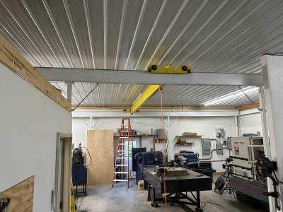
Bridge Crane build

I'm surprised that you have 'relieved' the center 1/2 (?) of the rollers.
How much safety margin is surrendered by supporting the bridge on the cantilevered flanges, rather than directly over the webs of the I beams?
 
I enjoy the process of designing something, the building it. The axles/rollers on the bridge crane trucks had me stumped for a bit.
This got rather complicated. I'm sure there is a simpler way to accomplish this, just not sure what it is.

That thing is looking good!

I cheated... lol
https://www.mcmaster.com/products/rollers/shaft-mount-track-rollers-5/
or
https://www.mcmaster.com/products/rollers/high-load-shaft-mount-track-rollers/
or
https://www.mcmaster.com/products/rollers/thrust-load-rated-shaft-mount-track-rollers/

(But, as we've discussed my design is fundamentally WAY different than yours so this may not have worked well for you.)
 
I'm surprised that you have 'relieved' the center 1/2 (?) of the rollers.
How much safety margin is surrendered by supporting the bridge on the cantilevered flanges, rather than directly over the webs of the I beams?
About the same as using a bottom hanging truck/dolley.

I'm more worried about off-center load causing a twisting/buckling moment in the beam. Either way, a wide roller or a hollow-centered roller can cause asymmetric loading if there is any bow in the beam (which there will be under load). As discussed earlier the solution to that is to narrow the roller, which I did so that this doesn't span the flange.
 
  • Like
Reactions: rwm
That thing is looking good!

I cheated... lol
https://www.mcmaster.com/products/rollers/shaft-mount-track-rollers-5/
or
https://www.mcmaster.com/products/rollers/high-load-shaft-mount-track-rollers/
or
https://www.mcmaster.com/products/rollers/thrust-load-rated-shaft-mount-track-rollers/

(But, as we've discussed my design is fundamentally WAY different than yours so this may not have worked well for you.)
Thanks Dan

I'd have to look through each of those carefully, but the rollers I've seen are all bearing mounted. I wanted to be able to drive the axle in case I later wanted to motorize the bridge. I'm not sure how you are handling that, I believe you had provisions?
 
About the same as using a bottom hanging truck/dolley.

I'm more worried about off-center load causing a twisting/buckling moment in the beam. Either way, a wide roller or a hollow-centered roller can cause asymmetric loading if there is any bow in the beam (which there will be under load). As discussed earlier the solution to that is to narrow the roller, which I did so that this doesn't span the flange.
To be bluntly clear, it doesn't matter. (I also got pinged on this via email)

Assuming that the roller is perfectly parallel with the beam face is not correct, as the bridge beam will bow under load. That means the roller will carry load more to the inside or out in most cases. So worst case it is carrying all the load on the outer edge, regardless of whether it is a single solid roller or a "relieved center". Thus, that is the design criteria. Since I already analyzed that to my satisfaction for the wide roller, the analysis doesn't change, in either case you have to assume the center carries no weight. This was the gist of a few posts a while back.

Everything else is just running around screaming about the crane falling (or the sky falling) without thinking it through.

I'm posting this as a design/build challenge, as I'm learning a lot about how design and build effect each other, and my machining skills get refined in that process. I already pointed out earlier in this thread (admittedly pages back), that I was going to stay clear of anything that sounded like a crane design tutorial, so I'm steering clear of engineering analysis details.
 
Last edited:
I'd have to look through each of those carefully, but the rollers I've seen are all bearing mounted. I wanted to be able to drive the axle in case I later wanted to motorize the bridge. I'm not sure how you are handling that, I believe you had provisions?

Yes, these are all bearing mounted.

Drive and clocking (=bridge square to rails) comes from a driveshaft on the bridge, and pair of roller chains on the rails. Chains lay on the rail, and are fixed at the ends. They loop over a sprocket on each end of the driveshaft.

The driveshaft is square, which allows a hand wheel drive to slide along the length of the bridge. (Well, most of the length, that driveshaft would sag if it wasn't supported part way. So 16' of range out of 24' bridge.)

That and the dual beam bridge greatly simplified the truck design, which is just square tube with rollers machined in near the ends. Because the bridge rails are almost over the rollers, the tube can be fairly light as it carries very little load.

At least that's the theory, anyway...
Sounds like a neat concept, i.e., a better approach!
 
Not sure it's a better approach, just a different approach.

I've run out of overhead room lifting things before, so that's what drove the dual beam bridge design (With a more complex carriage, I gain ~18-20 inches lift height). That requirement simplified other parts of the design, but added the cost of a second bridge beam (albeit both are smaller bridge beams).

The chain was just me puzzling out how to keep it square cheaply. A roll of roller chain wasn't very expensive, couple bearings and a shaft, etc.
 
Crane is basically assembled. Still some work in squaring, leveling and such before it's finally ready for use, but this is really the last step in terms of design/fab/build.
IMG_5187.JPG
 
Back
Top