Bridgeport or Knee Mill, VMC, Surface Grinder Owners.

[mention]Richard King 2 [/mention] Tell Prof. Slocum that Jason Melvin questions whether tripling the T-nut length will cut the contact pressure to one third, due to elastic deformation in the T-nut. That’s the only point in question here.
I cut and pasted what you asked.

It sounds as if he is teaching a class today, so I won't write him anymore. I am so tickled he considers me a friend.

From Alex Slocum

To:
  • Richard King

Mon 3/13/2023 9:38 AM


Ummmmm its a complex load situation, and compression causes squirt out sideways even if a plate on top of it.... and who knows how hard folks pulling on wrench (but your friend said "5000 lb" which jives with my spreadsheet....

anyway, nuff said-it is feasable it could cause warping over years of use... cast iron DOES plastically deform (bit it with a hammer and see the raised ding)

I am back to my day job!

alex
 
I would also like to hear Prof. Slocum's explanation your theory of how, a 3" tee nut would distribute a load exactly 3 times more evenly than a 1" tee nut? That theory seems not to consider for any deformation of the tee nut at all. Given the machine table is said to deform under pressure from the bolt I don't see how it would be possible for the tee nut not to deform as well.

Attached are a couple of engineering papers explaining, contact pressure distribution in bolted joints. There are dozens of other examples on the internet, all basically saying the same thing; the contact pressure drops off rapidly as distance increases away from the bolt, due to deformation of the joined material.
 

Attachments

  • AREAS OF CONTACT AND PRESSURE DISTRIBUTION IN BOLTED JOINTS.pdf
    4.9 MB · Views: 5
  • 15_Marshall_et_al_bolted_joints_Strain_2006_pre-submit.pdf
    442.5 KB · Views: 8
I would also like to hear Prof. Slocum's explanation your theory of how, a 3" tee nut would distribute a load exactly 3 times more evenly than a 1" tee nut? That theory seems not to consider for any deformation of the tee nut at all. Given the machine table is said to deform under pressure from the bolt I don't see how it would be possible for the tee nut not to deform as well.

Attached are a couple of engineering papers explaining, contact pressure distribution in bolted joints. There are dozens of other examples on the internet, all basically saying the same thing; the contact pressure drops off rapidly as distance increases away from the bolt, due to deformation of the joined material.
I'm out................
 
That theory seems not to consider for any deformation of the tee nut at all.
I think the difficult thing with the t-nut is that the loading and deformation are not nearly as simple as a bolted joint. So while I agree with you that one should not simply assume a 3x longer nut would reduce pressure to 1/3, getting to a more accurate result is not trivial. I know Prof. Slocum, having written my undergrad thesis for him, etc., and I'm not surprised he declined to surmise on what happens with the t-nut. That's why he used a spreadsheet to develop a first-order analysis for the contact pressure. I just don't like his assumption about the longer t-nut.

It seems undeniable that longer T-nuts will give diminishing returns, but also seems reasonable that going longer than 1" could offer a benefit. What I found interesting above was the possibility of contouring the t-nut contact surface to encourage a broader pressure distribution. It's also possible that the contact pressure on the table top exceeds the yield stress, which isn't an effect a longer t-nut could remedy. Just thinking about it, the effective clamping area could be about 1 sq. in. (a 1.625" diameter circle minus a 0.625" slot), which means pressure on the table top surface may exceed yield stress under some conditions. Again, not to say that this is what's happening, just to say that it's close enough to be possible. I think the issue with t-nuts is that they have a pretty limited contact area, so are more likely to have high contact pressure.

Any chance he would be willing to share his spreadsheet?
If you look at Prof. Slocum's FUNdaMENTALS of Design, you can download the spreadsheets and slide decks for a wide range of design issues. Some of the spreadsheets in Chapter 9 (Structural Connections and Interfaces) relate to the topic of this thread. The whole things is pretty great and I imagine many people in this forum would enjoy going through the full book.
 
I'm not going to ask him any thing else about this subject. Dr, Slocum told me I can share his spread sheet and I forwarded it to Gard. If he has a book with more info, please look there. I am sure he has a lot of other important things to do then discuss T-Nut with me. I won't ask him anything else.
From what he wrote on:
Mon 3/13/2023 9:38 AM

Ummmmm its a complex load situation, and compression causes squirt out sideways even if a plate on top of it.... and who knows how hard folks pulling on wrench (but your friend said "5000 lb" which jives with my spreadsheet....

anyway, nuff said-it is feasable it could cause warping over years of use... cast iron DOES plastically deform (bit it with a hammer and see the raised ding)

I am back to my day job!

alex,

It sounds as if JW is an MIT graduate, so he can take over....
As Charles said "I'm out too"
 
I don’t understand that attitude Richard. This is a forum, not a private platform. You started a thread and it spawned discussion directly relevant to the thread. You didn’t agree with some people and so you now want to stop them, but that’s not how forums work.
 
I think the difficult thing with the t-nut is that the loading and deformation are not nearly as simple as a bolted joint. So while I agree with you that one should not simply assume a 3x longer nut would reduce pressure to 1/3, getting to a more accurate result is not trivial. I know Prof. Slocum, having written my undergrad thesis for him, etc., and I'm not surprised he declined to surmise on what happens with the t-nut. That's why he used a spreadsheet to develop a first-order analysis for the contact pressure. I just don't like his assumption about the longer t-nut.
I agree, the forces on the tee nut is not a simple calculation, that's why I am baffled Prof. Slocum would have such a rudimentary formula in the spreadsheet?
It seems undeniable that longer T-nuts will give diminishing returns, but also seems reasonable that going longer than 1" could offer a benefit. What I found interesting above was the possibility of contouring the t-nut contact surface to encourage a broader pressure distribution. It's also possible that the contact pressure on the table top exceeds the yield stress, which isn't an effect a longer t-nut could remedy. Just thinking about it, the effective clamping area could be about 1 sq. in. (a 1.625" diameter circle minus a 0.625" slot), which means pressure on the table top surface may exceed yield stress under some conditions. Again, not to say that this is what's happening, just to say that it's close enough to be possible. I think the issue with t-nuts is that they have a pretty limited contact area, so are more likely to have high contact pressure.
I agree a longer nut could possibly distribute the some pressure over broader area, I just don't see the even ratio as being possible.


Thank You for posting the link to FUNdaMENTALS of Design, very interesting and it will certainly be helpful.
 
I agree, the forces on the tee nut is not a simple calculation, that's why I am baffled Prof. Slocum would have such a rudimentary formula in the spreadsheet?
Because it was easy and he has other things to do with his time, I’m guessing. He is almost always running on all cylinders.
 
I suggest we do some experimenting. Next time you tighten your vise on your mill table, mount a mag base on the side of the quill and put a .0001" indicator on the side of the T slot next to the T-nut and tighten it. See how much it moves. I am telling you this happens and with my 50+ years of experience I say it happens. You can take it or leave it.
The short answer is yes. I did a test and got a repeatable result. The table did deform in the area near the tee nut when the vise was clamped down. However, it was very slight, only .0001" (1/10,000") and the deformation went away when the nut was loosened up again. The vise in relation to the spindle did not move in the Z axis at all. So in a broader picture, the error is negligible and doesn't appear to be permanent, at least in my case.
How I did the test:
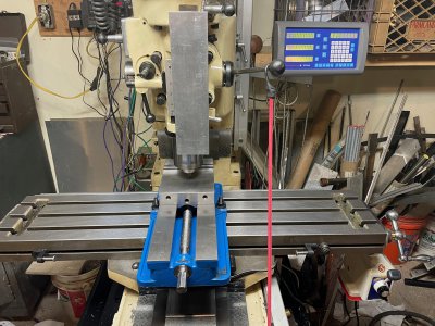
My mill is a RB-1 (Aka, First), basically a Bridgeport hybrid in a bed mill configuration, instead of a knee, It was manufactured in 1987 by Long Chang Machinery, Taiwan, It is very well made machine with Meehanite castings and chromed ways. It is in excellent condition.

After removing the vise I stoned and cleaned the table, I checked the table for any existing warpage. I used a 24" Starrett straight edge, I know its not a "scraped-in camelback" but I checked both edges on my granite surface plate, it was very flat not rocking or pivoting at any point, I could not get a .0005" shim under it at all. I got the same result on the mill's table, no discernible humps or high spots, the shim could not get under it at any point except in the flaking divots. When I deliberately put the shim under the rule it would distinctly pivot on spot. I moved the rule a few inches at a time, end to end and across. So I can safely say the table is flat to less than a half a thou in any 24"
MC TS - 1 (2).jpegMC TS - 3 (1).jpeg
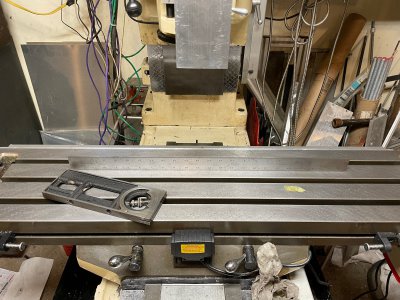
Next, I checked the way travel by setting a tenths reading indicator on a magnetic base set on the bed and swept the movable length of the table, there was a slight rise at the far limits of travel about .0013" with the table moved all the way to the right and about .001" when moved all the way to the left. This is expected as the weight of the table hanging off one end causes the opposite end to rise slightly, this error only appears in the last few inches of travel. For most of the travel, the table showed no average change. Note, the leftwards travel is limited due to the X-axis power drive unit, that's why its error was slightly less.
MC TS - 5 (2).jpegMC TS - 7.jpegMC TS - 1 (4).jpeg
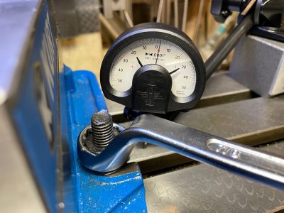
Next I mounted the vice back on, the center of the table first stoning and cleaning the bottom and then tramming it in. Both a vertical and horizontal sweep of the fixed jaw showed almost no movement with a Starrett last word test indicator .0005" res. Then I loosened stud nuts and set the indicator on the top center of the find jaw and retightened the nuts nuts, no visible movement on the indicator. Then I thought the quill's DRO has a 1μ .00005 (5/100,000") resolution, So I made a probe out of an inverted end mill and a ballbearing set in the center recess, I chucked it in the spindle and rested it on the top of the vise inline with the bolts. I put a bungee cord on the quill lever to put constant pressure I tightened the bolts and I got about .0001" rise. However on closer inspection I realized the ball bearing had made a small dent in the top of the vise and when I tightened the vise there was a slight movement on the Y axis causing the ball to ride up on the side of the dent and give the false reading. I then stoned the top of the vise and placed a square of carbide for the ball to rest on. Subsequent tests could not show any movement in the Z axis.
MC TS - 2 (1).jpegMC TS - 1 (3).jpegMC TS - 3 (2).jpeg
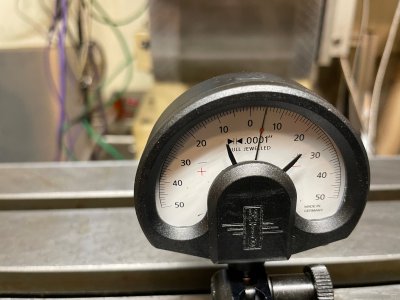
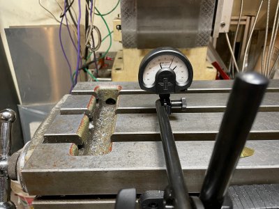
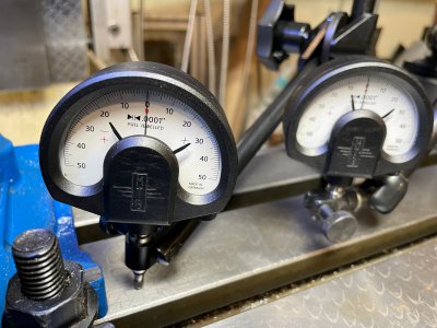
Next I checked the table around the area of the vice hold down nuts, with the probe, I got a .00005" rise but the diameter of the quill prevented me from getting in close and was in the way of the wrench. So I switched to tenths reading indicators, placing one as close to the nut as possible and one a few inches away as a control. Tightening the nuts showed a .0001" rise on the close indicator and no change on the far indicator. I repeated the test several times with and with out the probe on the vice and the nuts on both sides of the vice. All results were consistent, a one ten-thousandth bulge/distortion in the table surface at the immediate area around the nut, but no change in the vice itself.
MC TS - 2.jpegMC TS - 3.jpegMC TS - 4.jpegMC TS - 5.jpeg
Given these results, I did not proceed to make larger tee nuts to see if the they would "help" as the distortion was so insignificant, went away when the bolt pressure was relived and didn't affect the vise in any way. I don't think it's an issue for me. Of course these are my results, on one machine. IMHO The theory is still viable as a different, weaker table could possibly distort more and even retain some of that distortion. Anyone concerned should conduct their own test.
 

Attachments

  • MC TS - 4 (2).jpeg
    MC TS - 4 (2).jpeg
    404.1 KB · Views: 2
  • MC TS - 5 (1).jpeg
    MC TS - 5 (1).jpeg
    643.4 KB · Views: 2
  • MC TS - 6 (1).jpeg
    MC TS - 6 (1).jpeg
    525.4 KB · Views: 2
  • MC TS - 6.jpeg
    MC TS - 6.jpeg
    441.2 KB · Views: 2
  • MC TS - 2 (3).jpeg
    MC TS - 2 (3).jpeg
    611.1 KB · Views: 2
  • MC TS - 1.jpeg
    MC TS - 1.jpeg
    466.7 KB · Views: 3
Back
Top