Bridgeport or Knee Mill, VMC, Surface Grinder Owners.

Here is another one.. Listen to what he says about 4 minutes ...the table droops.
.008" Also at 16 minute he tells you the same thing I told you. Steve hosted 5 of my classes. Around the 28 Minute mark youcan hear the middle hits first. He also says he rebuilt 2 machine that the table was not bent. Also around the 30 minute mark you can see it is only in the middle
 
Last edited:
Richard, I think we agree that tables droop. We also believe that many operators don't realize that they droop, or how much they droop. We seem to agree that over a short amount of x-travel, the effects are not apparent.

To properly rebuild a table, you need to do two things, restore the flatness of the table top, and restore the ways parallel to the top, sides, and T-slots (longitudinal axis). I don't know the proper order for those two operations, but doing one without the other will not restore accuracy.

Let me relate a real-world experience to explain why I asked the question in the first place.

I bought a Wells Index 847 that had been "rode hard and put away wet." I knew it had been used a lot near the center of X-travel, because the Acme lead screw threads had been worn to sharp points in that area, with a correspondingly huge amount of backlash. To get a rough idea of wear on the ways, I put a dial indicator against the table top and moved the X-axis full travel end-to-end, expecting a large deviation and the table "falling" in the center and "rising" at the ends because of wear. Imagine my surprise when I found no significant deviation over the entire travel! There were local deviations from physical damage to the table top, and a couple of places where the top rose slightly, then dropped back to zero. I now know, from your report, that these rises could come from distortion from clamping forces.

Since the mission profile of this machine is to repair equipment used on our Tree Farm, it is accurate enough for my purposes, so I left it there. This experience is why I asked the question. Normally, one would expect the effects of wear to "stack" the deviations, but under certain circumstances, it is possible for them to cancel out. I wouldn't expect the effects to be predictable or repeatable, but they are possible. I also don't believe that anyone should use this information to assume that a worn machine is accurate enough to hold a tolerance without further analysis and inputs from an experienced operator.
 
Richard, since you will have a table set up on a big surface block, it would be interesting to measure the wear on the contact surfaces of the ways. I would then be possible to compare the measurements of the arch of the top of the table to what is happening at the ways. It would answer the question of how the bow and wear interact.
 
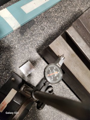
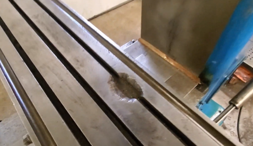
Heck I didn't need you to tell me that, as this isn't my first rodeo. I tested the one table that Cameron brought. We set the table T-slots down on 3 points on the granite plate and made the 4 corners zero or all the same. We had to move the single side point (3 points) out similar to what Steve Watkins did on his You tube show as the top of the table was bent. Then we indicated the flat ways and the table was worn .007" in the middle or low. Then I moved the indicator to the T- Slot side that was setting on the 3 point blocks that were the same thickness.
Measuring the top T-Slot side and it was bent .005". So the bottom or wear side was worn .002" and bent .005" . I took pictures but screwed up trying to email them from my cell phone to my laptop here in the Hotel room. I will figure it out and attach some pictures later. I am so fricken tired. I got one to work. I may have to wait until this weekend when I'm not to tired.
 

Attachments

  • 20230322_143430.jpg
    20230322_143430.jpg
    347.8 KB · Views: 9
Last edited:
Thanks Richard!

When I was younger, I didn't mind going places. Now that I am older, I'm hard to pry away from my home, and especially the wood stove in the winter!
 
Proposed theory of table warpage
Tightening T nuts in the table results in local compression of table T slot flange. The compression causes a small area of the flange to get slightly wider (longer). After many cycles at various points along the flanges, there is enough stressed area to cause a permanent bend of the table.

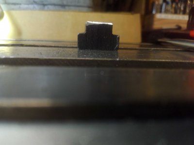
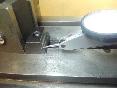
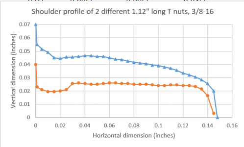
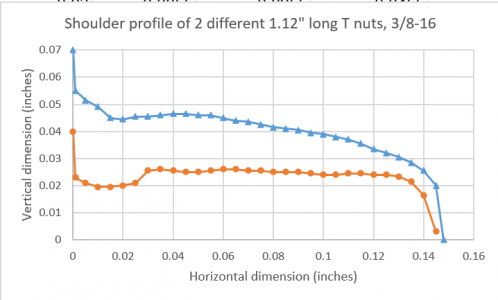
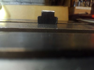
There has been much well justified discussion about the root cause being excessive bolt torque and distortion of the T nuts. The back of the envelope type calculation from Prof Alex Slocum suggests that even with over tightened bolts, the stress is barely enough to cause damage even with low strength cast iron. He suggested a test of the iron to verify its strength. I would like to suggest a possible related contributing factor which is the bearing quality between the T nuts and bottom of the flange. None of the T nuts in my modest collection are flat on the bearing surface. Should they be? They will likely only contact the bottom of the flange at a couple of small points or lines. Even a modest bolt torque will likely cause a small dent in the cast iron at these points. Can multiple small impacts over the years result in a warped table? As described by tq60

At one time, we worked in an automotive machine shop, and one of our jobs was straightening crank and cam shafts.

We used a chisel and ball pien hammer, the chisel was placed at the low spot and tapped.

This relieved stresses, and the shaft would come TOWARDS the chisel.

If this is a potential contributor should the T nut flanges be ground flat or is there some reason why they are not? Here is a couple of my T nuts

KIMG1688.jpgKIMG1691.jpg1679600590276.png

I have been using 6061 -T6 aluminum for my 5" bridgeport vise on a clausing mill. I have indexing blocks, and the aluminum seems to lock into the tslot pretty good, so I don't need to gronk on it. I usually need to play with the tnut to get it to release. So I think the hard cast iron and softer aluminum lock it in pretty good. I wonder if that would also negate the situation. Can't tell as who knows how many owners and what type of work this mill did long ago.
This seems like it would be another good possibility, make the T nut from something softer than cast iron (aluminum or brass). Or steel with a gasket. The dents due to surface irregularities will all be in the aluminum instead of cast iron. These would be somewhat disposable as they got worn out.

What effect does table bow have on milling machine accuracy? As a thought experiment, assume the table is warped or bent. An indicator is mounted to the quill and the table is moved across its range. The indicator reading will not change because the thickness of the table (distance to saddle) is uniform. A series of small parts clamped to the table will be machined to a uniform height. A long straight part held in a vise will not be parallel to the bent table over its length so its surface will be machined into the same curve as the table.
I have seen this effect on my small mill when attempting to machine straight edges prior to scraping.
I have done some measurements where I have seen the table warp as the T nuts are tightened, will post as time allows.
 

Attachments

  • 1679599632166.png
    1679599632166.png
    29.6 KB · Views: 3
  • KIMG1691.jpg
    KIMG1691.jpg
    346.2 KB · Views: 4
  • KIMG1688.jpg
    KIMG1688.jpg
    254.7 KB · Views: 4
Great post [mention]gard [/mention] and exactly hitting the points I find interesting. If the bottom of the t-slots are well finished, then a t-nut’s contact surfaces could be designed for a smooth pressure profile even as the t-nut deflects when tightened. Your idea of a conformal layer may be easier/better still.
 
Great post [mention]gard [/mention] and exactly hitting the points I find interesting. If the bottom of the t-slots are well finished, then a t-nut’s contact surfaces could be designed for a smooth pressure profile even as the t-nut deflects when tightened. Your idea of a conformal layer may be easier/better still.
Thanks for that Jwmelvin
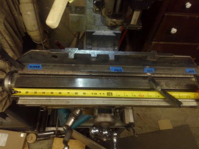
I have a Clausing 8520 mill with 24x6 table that uses 3/8 clamping bolts. A straitedge pivots in the center and when one end is lightly clamped to the table a 0.005" shim will fit under the opposite end suggesting a table bow of about 0.0025" high in the center. This is consistent with what I saw attempting to machine straight edges.

KIMG1687.jpg

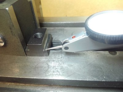
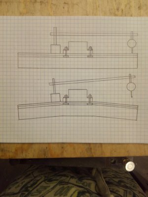
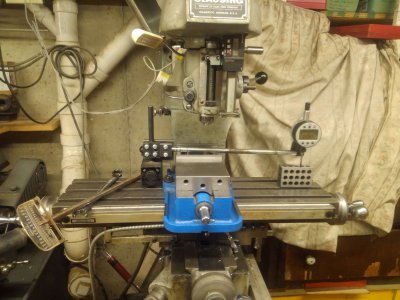
It seemed possible to me that a high enough T nut clamp force might cause an immediate elastic bending of the table that could be measured. I assume the bending will be limited to small areas under each T nut. A 4 inch kurt vise is clamped near the center of the table. An indicator base is mounted to the table on one side of the vise with a tenths indicator on the opposite side. Here is a conceptual cartoon and photo of the setup. The top sketch is with the vise bolts loose and the bottom sketch is after tightening the bolts and bending the table.

KIMG1694.jpgKIMG1692.jpg

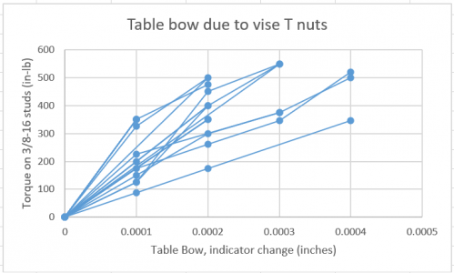
The indicator was recorded as the 2 vise nuts were torqued down. In general I could see the indicator increase as the torque is increased in several steps and return to zero as the bolt is loosened. I repeated the experiment with different T nuts using the same lightly oiled flange nuts and studs. The vise was moved to different locations on the table. For some tests I added thin shims between the vise and table to prevent the vise from straightening the bowed table. I don't have a good explanation of why the results are so variable with deflections ranging between 1 and 4 tenths at around 400 in-lb torque. The less flat T nuts and additional shim seemed to result in more deflection.

1679615457597.png
It is clear a more sensitive indicator is needed to really see what is happening, along with load cell washer under the bolts. Neither of which I currently have access to. I have not attempted any calculation to try to predict this elastic deflection, I may give that some thought.

A rough calculation based on torque and perfect contact suggests about 18,000 psi which should be below the compressive yield stress of most kinds of cast iron. This suggests that if there was perfect contact between the T nut and flange it would be unlikely to cause permanent bending of the table (not impossible).

A couple of questions
Anyone ever try straightening a bent milling machine table for example using a hydraulic press?
Anyone know what kind of cast iron these tables are typically made of? Any estimate of hardness or better yet strength?
 
Back
Top