- Joined
- Jul 26, 2011
- Messages
- 4,142
I angle my internal grinding wheels a little .
Do you dress a narrow surface on the corner then before grinding?I angle my internal grinding wheels a little .
Having done a lot of ID and Jig Grinding in the past. I believe many people angle their tool post grinder because it puts less of a stress on the grinder to eliminate any possible belt slippage for those using a belt. By angling the the tool post grinder you will be using less of the wheel and thus causing any wear down to happen at quicker rate. This may not be a problem when doing a single part but can be a bother if doing multiples. By going straight in the end will wear down first. leaving the rest of the wheel to do less work and finish the hole.
Or at least that is what I was taught.
 ) says to angle the wheel slightly and dress a narrow edge flat, then grind with this dressed edge.
 .
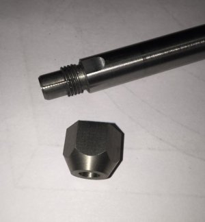
.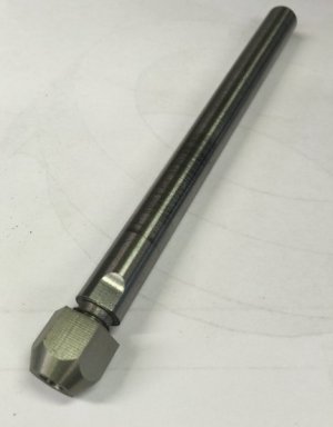 This is the completed arbor with a chuck on the end. It is made entirely from drill rod , so I can harden it if I choose or need to. Note the wrench flats on the end of the shaft. They fit a 7/16" wrench.
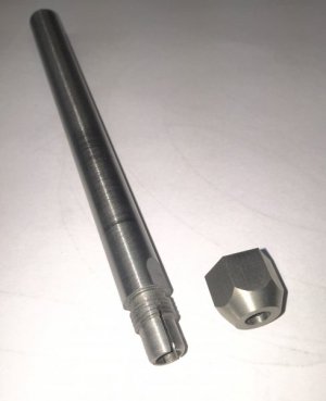 The shaft is 8" long of 1/2" drill rod ( to fit the 1/2" ER20 collet). The end was reamed .250" for 1 1/2" deep. Then threaded 7/16-20. The end was turned down to 25/64" and beveled 30 degrees on the end.
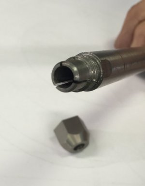 I used my Dremel with a thin cut off wheel to cut three slots , 120 degrees apart. The nut was made from .750 drill rod. Drilled with a custom ground drill bit. The bit was ground with a 30 degree angle to match the end of the chuck , then tapped 3/4 of the depth with a 7/16-20 tap.
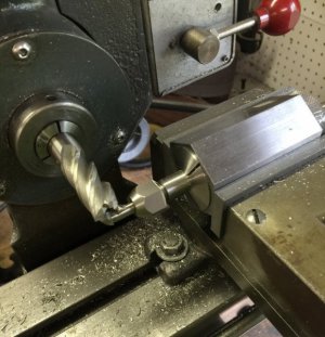
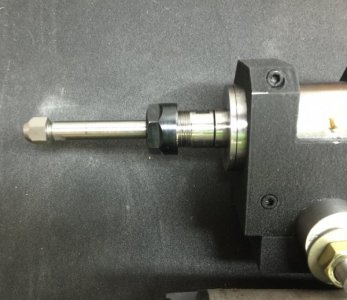 The arbor fits my grinder spindle perfectly. I can extend or shorten it as needed.
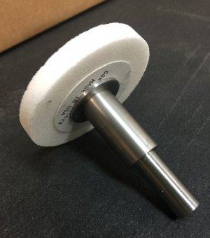 I also need an arbor to hold my 3" diameter external grinding wheels. I used a piece of .750 drill rod for sturdiness . Turned one end to .5000 " to fit the grinder spindle. I left a 1.50" center section.
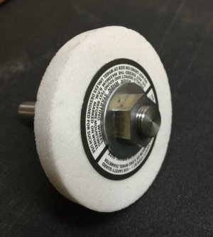 The other end was turned to .5000" diameter to fit the grinding wheel. I then threaded the shaft 1/2-20 leaving a .500" long shoulder for the wheel to register on. The washers are a pair of good quality heavy 1/2" washers that happen to be a close fit on the shaft. I stoned both sides of each washer flat then mounted on the arbor with a spacer and turned the OD true. The nut was a good fitting grade 5 nut and machined thinner to be less bulky.
There is no tapered shaft..... The collets hold tight.I hope the tapered shaft has a draw bar! You don't want that flying out at high speed!
When I make those,I save a little metal to grind out while the arbor(s) are running at full speed. It is hard to get them to run really true after they are running at high RPM. Variations in the density of the metal is enough to throw them out of true when they are run very fast. The tiniest variation is greatly magnified by centrifugal force.
On post #77,what is a "deemed"?
On post #77,what is a "deemed"?
