- Joined
- Feb 5, 2015
- Messages
- 662
Turning A Sphere With The Lathe Compound
Ball-turning mechanisms turn up on internet forums and personal websites often; the design/construction challenge doubtless provides much satisfaction but I wonder about the actual utility of these tools. Turning a ball on a lathe is rarely required for reasons other than decorative ones (exceptions to follow) and most lathes already have this ability with no need of special tooling.
Small lathes traditionally were able to produce both concave and convex configurations but the ability has gradually been forgotten by hobbyists - perhaps due to lack of necessity BUT also because of modern tooling preferences.
For many years, off and on, I've used an "Armstrong" tool post, a useful device for several reasons - not the least of which was the ability to turn radii. Here's a description, from memory, of setting up a lathe for radius turning with the "lantern".
Alignment is relatively simple: an adjustment of the toolpost (and the tool), loosening the compound lock nuts then setting the cross-slide appropriately allows turning concave and convex radii over a fairly large range of useful dimensions. It is also fairly simple to "zero" the radius setting of the compound slide using a center in the headstock spindle. It's helpful to have a good imagination of three dimensional geometry, LOL, when setting up for radius turning !
Adjusting the compound slide and carriage while rotating the compound (about 90 degrees, back and forth), the pivot point of the compound can quickly be found by comparing the path of the cutting tool to the fixed point of the headstock center. During this process, the cross-slide must be adjusted to bring the tool gradually nearer the headstock center point - take care not to bang the tool into the center. When the compound slide is adjusted so that the cutting tool is exactly over the pivot point, the point of the tool will not move - relative to the headstock center - as the slide is rotated.
At this point, the dial of the compound slide can be adjusted to zero. Any desired radius - concave or convex - can now be easily dialed off with the compound crank (observing backlash considerations, of course) and the radius turned by manually moving the compound about its axis, advancing the tool into the cut with the carriage by hand until the finish radius is obtained. This sounds more complex than it is - takes less than two minutes to adjust and "zero" the compound for radius turning with the Armstrong.
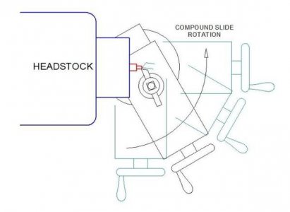
Without the Armstrong toolpost, the process becomes more difficult to envision. The axis of rotation (of the compound) and where the cutting tool is located relative to the axis is important for understanding what radius your machine can produce using this method. It might be helpful to loosen the compound retaining nuts and pivot the compound slide while adjusting the slide in and out. Observe the cutting path that the cutting tool "traces" in the air and you'll quickly grasp the geometry of the process.
The four-way toolpost and the quick-change toolpost do not allow rotating the compound slide to cut small radii. The tip of the cutting tool is located too far from the pivot point of the compound to enable cutting radii smaller than about two or three inches.
Simply stated if the cutting tool cannot be adjusted so that it is directly above the rotational axis of the compound, cutting small radii - either convex or concave - is not possible. This rules out almost ALL tool holders except for the good old Armstrong lantern.
OK, so much for the historical lesson, and why people make radius turning attachments.
Occasionally one may need to produce spherical shapes with a QC or 4-way tool holder. There are a couple of ways to do this without a ball-turning tool. That is not to say that a ball turning tool - of whatever design/construction - isn't useful. I'm sure that it must be for those who do more decorative work than me otherwise there wouldn't be so many different designs on the internet.
Cutting A Sphere By Incremental Steps
This simple method is one that has been used for many years. It was especially useful when I was a part-time machinist in a job shop making various sizes of custom pipe-bending dies (back in the late sixties). It is a manual method of performing an operation that a CNC lathe routinely performs by stepping off the appropriate "X" and "Y" distances, producing an approximate radius of the prescribed dimension. The advantage of this method is that radii of any dimension within the capability of the machine can be turned - no special tooling is required. The degree of precision is dependent only on how small one wishes to make the stepping increments.
Because the occasional ball/socket joint can be useful (and lacking an Armstrong toolpost for traditional radii turning) I made a spreadsheet for calculating cross-slide travel while indexing the lathe carriage in small, fixed increments. The spreadsheet allows user entries for the variables (the entries shown in blue) and calculates the remaining dimensions (shown in red). Here is a sample of the spreadsheet with entries that I used to produce some small ball joints a few years ago:
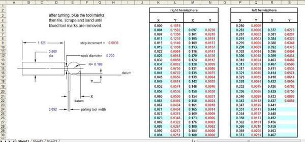
Note that when the parting tool approaches the neck diameter (relief diameter) that is specified by the user, the spreadsheet will no longer display the "Y" dimension. This is to prevent plunging below the relief diameter and ruining the part. A copy of the spreadsheet can be downloaded from this site:
http://www.webfilehost.com/?mode=viewupload&id=9683478
This is an application for the ball-joints that motivated the spreadsheet. I made three of these for Christmas gifts; they are a combination of metalworking and woodworking, like many of my projects. These are cookbook stands made for several in-laws. The "wands" on each side of the stand hold the books open at the desired page and also serve as paragraph markers, pointing to the desired recipe on the page. Steel ball-joints are spring-loaded with adjustable friction mechanisms so that they stay put when they are positioned on the page.
The ball-joint mechanism is not visible in the photograph, the parts are contained within 3/4 diameter aluminum cartridges that thread into the wooden frames. The cartridges are just visible on either side of the frame.

The machining method is straightforward: a parting tool is "touched off" the work diameter (after it has been turned to finish dimension) and the cross-slide graduation is zeroed. Next the parting tool is "touched off" the face of the work and the travel indicator (the "X" axis) is zeroed.
(Incidentally, although I've not bothered to do this, a simple change to the spreadsheet would allow making concave cuts - as in the pipe bending dies that I mentioned previously. For my purposes, I use ball end mills and router cutters to ream sockets for ball joints. The mills are held in ER-40 collet chucks, adapted to the lathe tailstock.)
The rough profiling process commences by plunging the parting tool to the determined depth (from the spreadsheet) after moving the carriage the initial increment shown in the spreadsheet. From then on, the carriage is moved to the dimension shown on the spreadsheet and the parting tool is plunged the incremental amount shown on the spreadsheet, applying a little coolant as required. Obviously, the finer the increment, the better profile obtained.
Losing position isn't a problem … a glance at the cross-slide handwheel or the travel indicator and comparing the reading with the spreadsheet confirms which step I am cutting. The left hemisphere (if it is required) is turned, step by step, until the neck (relief) diameter has been reached. For the sample part below, I didn't cut the left hemisphere - only s relief groove was required.
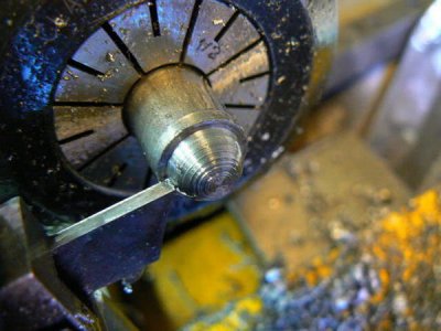
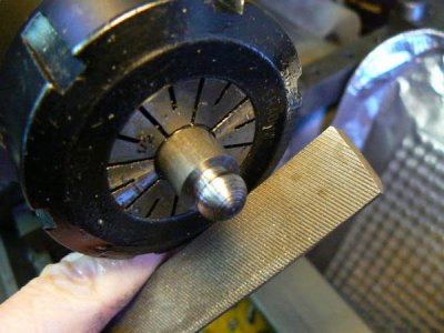
At this point, the workpiece will be roughed out properly and some handwork will quickly complete this part of the process. First, blue the machined surface (a broad-tip "Sharpee" felt tip pen is a practical alternative to layout dye). Use a file to work the sphere in a rolling motion as the lathe spindle is turning slowly.
After ten or fifteen seconds the work will take on the appearance of a series of parallel lines across the ball and the line width will diminish as the high points are reduced. When the lines are so narrow as to be nearly invisible, the process can be completed by increasing spindle RPM and sanding to the desired surface finish. The part in the following photo is ready for sanding.
With patience it is possible to achieve a spherical tolerance within .003 inches using this simple, primitive method. Here's the result after sanding - the application doesn't require a finer finish than this …
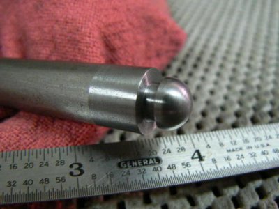
The simple part required about twenty minutes to make, including entering appropriate information into the spreadsheet. That doesn't sound like a lot of time but frankly it's a boring experience - this technique is not recommended for those lacking patience, LOL, but it can be useful.
One of the most common decorative profiling operations performed on a mill is fluting - a rotary table isn't usually required for this. A hex collet block, for example, can be used to index a workpiece and even simpler methods are practical for decorative indexing. (Sorry about the shakiness of the photo.)
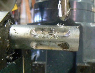
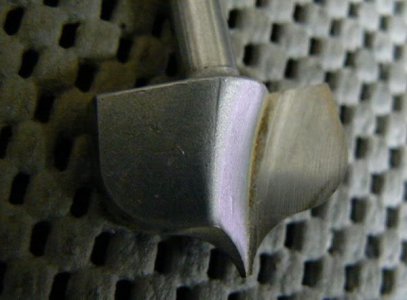
The above was produced with a HSS 1/2 ball end mill; many more interesting configurations could have been produced with a router cutter, like the one shown below, especially when the cutter can be angled or offset from the spindle axis. Because this is an older HSS cutter with 1/4 shank and without helical rake, I wouldn't normally use it on any work harder than aluminum, at least for a milling operation; it would work OK in the lathe as a forming tool.
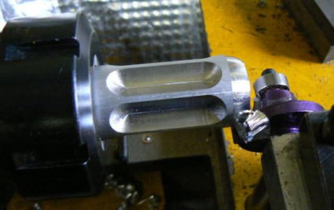
After fluting with the ball end mill, the work was placed in the lathe briefly to form a decorative end (with a router cutter in a 1/2 boring toolholder). As will be shown later, this operation could also have been performed in the mill.
Sometimes it's a pain to move a heavy rotary table to a machine for indexing that doesn't require high tolerance. If a collet block or other indexing device isn't available, it's possible to index a workpiece by simpler means. It has become common practice in recent years to print full scale CAD sketches, adhering them to a workpiece for layout purposes. (In times past, we would have blued the work then made a layout on the surface plate using an angle plate, vernier height gage and other layout tools.)
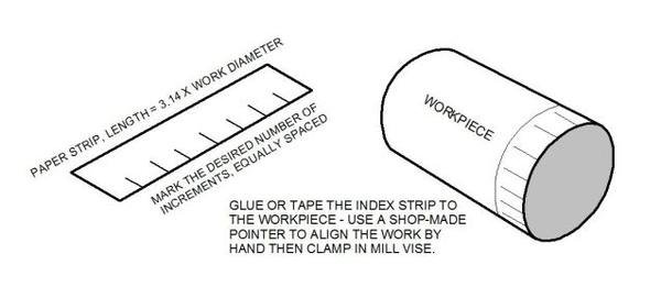
Similar means can be used for indexing purposes, CAD generated or layed-out by hand using normal geometrical construction, provided tolerances are not critical (e.g. decorative applications). The sketch below is a typical method of indexing by hand … the round part is clamped in the milling vise and a temporary pointer used to align the index mark on the part. After the operation is performed, the vise is loosened, part rotated by hand until the next index mark is aligned and so forth …
With a little luck, there may be a gear in the junk box that can serve as an indexer. For example, by skipping over the appropriate number of teeth, a 48 tooth gear can produce the following division ratios: 48, 24, 16, 12, 8, 6, 4, 3 and 2. Temporarily attach (contact cement, super glue, soft-solder ?) the gear to a shaft collar of the same I.D. as the workpiece. Attach the gear + collar to your workpiece using the shaft collar set screw. A temporary pointer can be used to align the index marks. Use your imagination to devise a convenient means to index the work.
The fluting example is an illustration for this particular post but I hate to waste time and material so I recycled this part into something useful. Incidentally, I like to dip some parts in a shellac/alcohol, to give a gold tint similar to "Alodine 1200" (followed by a coat of clear poly for wear protection if necessary). After tapping the other end, this part replaced a lost item on my camera tripod.
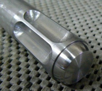
Visual interest or functional purpose can be added by angling the part slightly in the mill vise, producing semi-helical flutes across the workpiece. Special cutters, reamers, counterbores and so forth can be made from drill rod using this method to obtain optimum cutting geometry. Here's a counter-bore that illustrates this concept.
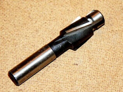
In the above photo, although the flutes appear to be helical, they are not. A straight edge placed against the edge of the flutes would reveal that they were milled at an angle rather than using a geared indexer.
A rotary table on the vertical mill can produce interesting and functional shapes using standard end mills (and router cutters). As noted in the first part of this profiling thread, many types of older router cutters aren't appropriate for milling - more modern routing cutters have a helical cutting edge which is desirable for milling.
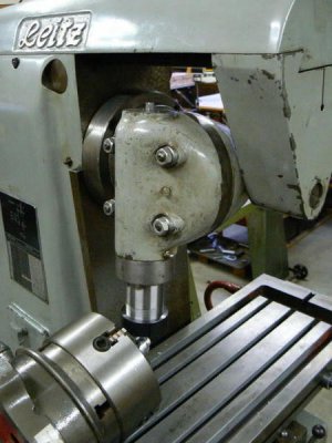
Note that the large size of the four-jaw chuck in this set-up prevents the vertical head from getting close to the workpiece without interfering with the jaws. One way of getting around this problem is to use a smaller rotary table and/or smaller chuck/collet system.
Those options were not available at the time I was preparing this post so I used a simpler technique and installed an ER collet chuck in the vertical head. (It is a coincidence that the vertical head for the horizontal mill has the same taper as my lathe tailstock - for which the ER-40 collet chuck was actually purchased).
The extended length of the ER-40 collet chuck can sometimes be a problem but it is an advantage here, allowing the cutting tool to easily reach the workpiece despite the large chuck and rotary table. The direction of rotation of the table should oppose the rotation of the cutter (conventional milling, not climb cutting). The finish pass can be climb-milled after taking up the backlash on the rotary table the with worm eccentric.
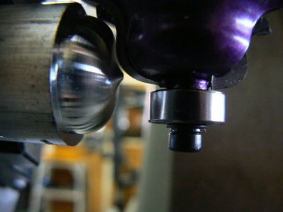
Here's the decorative part after a few seconds polishing with 000 steel wool:
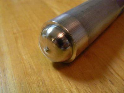
By angling the rotary table a simple set-up using a boring head can quickly and precisely produce balls in a vertical mill using a generating process. The process can be more geometrically accurate than typical lathe ball-turning mechanisms produce. The sketch below represents one ball-turning configuration (an angle I have found useful for ball-joints). The dimensions are "normalized" so that the critical operations are all related to the diameter of the ball. Any diameter ball can be produced by multiplying the ball diameter by the constants shown on the sketch.
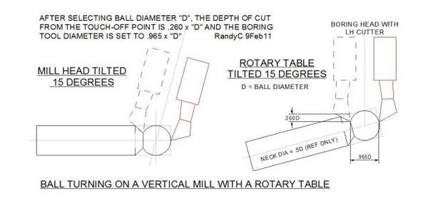
After centering the spindle axis on the rotary table axis, all that's required is "touching off" the boring tool at two places to establish a reference. Downfeeding the boring tool incrementally while cranking the rotary table can produce the ball profile in a few minutes.
Note that the boring tool requires a left hand boring bar rather than the normal configuration for normal spindle rotation. (Of course right hand boring tools can be used by reversing the rotation of the spindle.)
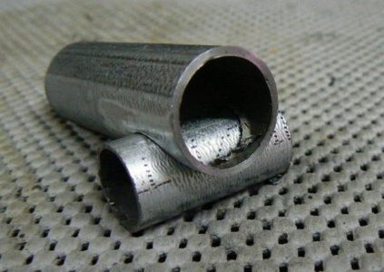
Although this isn't directly related to profiling, many of us have used this little trick: small hole saws - if they can be held in a collet without an arbor - can be useful to cope pipe and tubing for weld preparation. A hole saw supported in an arbor is not a very rigid tool for interrupted cuts - typical of coping operations. A hole saw, if it is small enough to be held in a collet can be a different proposition due to the enhanced rigidity.
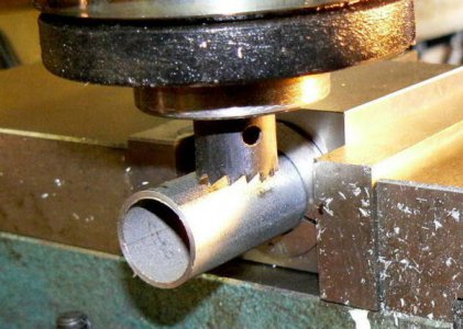
This particular hole saw is too short to plunge through the part, it was plunged half-way and then the part was inverted in the vise to continue the cut. Here's the finished part - no de-burring necessary since it is to be welded.
With the spindle running at about 600 RPM and using a bit of sulphur-based cutting oil, the hole saw cuts almost as fast as if it were cutting wood ! There are better tools available for coping tubing but because I don't require this function often, I make do with what is in my tool inventory.
Adding a rotary table to the profiling situation introduces more flexibility - contouring can be easily performed while rotating the workpiece in the rotary table. Not that there is no advantage of a hole saw over an end mill for this application unless large radii are required. For large radii, a sturdier arbor than the flimsy ones typically provided with hole saws is required. I made this one for a four-inch diameter hole saw.
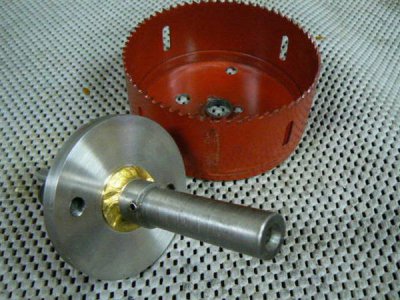
The arbor shank is 3/4 diameter, the shoulder is 3 inch diameter and a 1/4 reamed diameter was included for a removable pilot. This feature was included primarily for coping operations, using a lower guide bushing to maintain stability for operations applying side loads.
Some may question the fact that the parts were brazed, not welded. At the time that I made this tool, I didn't yet own my excellent Miller 211 and my only welding options were O/A torch or a small 115 volt MIG. But the brazing process probably resulted in less distortion since all of the parts were well heated by the torch before I started laying down the bronze, LOL.
The arbor worked OK and I later modified a couple of 10 inch saw blades to run on the same arbor by drilling holes in the blades for the two mounting screws, using a carbide drill. The 5/8 pilot for the saw blades was the same diameter as the pilot for the hole saw, so the arbor was suitable for both applications.
(A tip about carbide drills: masonry drills from the local hardware store are inexpensive and work well for uninterrupted cuts. But the carbide edges usually chip as the drill breaks out the far side. Either back up the part with a scrap that is near the same hardness or drill part-way through the hardened part then turn it over and drill from the opposite side. A little care when the intersection of the two holes is reached can prevent chipping the corners of the drill.)
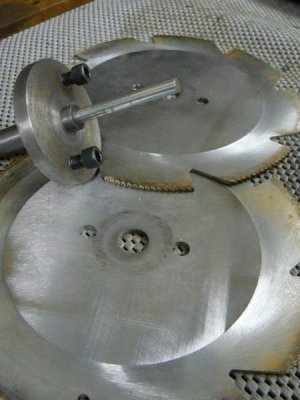
I suppose that this operation can be described as profiling, LOL. The blades were stacked as "dados" for making "box joints" on guitar amplifier cabinets using the vertical mill. (As I've noted before, I'm not reluctant to use metalworking tools for woodworking and vice versa.)
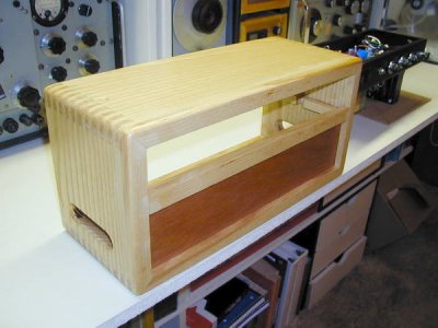
Although I have no photos of the box joint operations on the mill, here's a vacuum tube amplifier cabinet prior to finishing; the box joints are visible. It's time-consuming to do cabinet work with a milling machine but the finished result is worth the effort when only a few are produced. (All of my amplifiers were designed and built as gifts - not for sale.)
Many people use large rotary tables to perform operations that a lathe might be incapable of performing - truing up large diameter flame-cut circles with carbide insert mills comes to mind. Small procedures can also be easily performed with a rotary table - there is almost no lathe contouring operation that cannot also be performed on a mill with a rotary table and the proper cutting tool.
There's much more to the topic of profiling and contouring on both lathe and milling machine using common tooling found in most hobbyists shop. I'm not expert at these things but I've learned to make-do with what is available. (Especially when times were lean and the only machine tools were an Atlas six-inch lathe, Craftsman arc welder and a Craftsman variable speed drill motor with a home-made stand vaguely resembling a drill-press, LOL.)
Ball-turning mechanisms turn up on internet forums and personal websites often; the design/construction challenge doubtless provides much satisfaction but I wonder about the actual utility of these tools. Turning a ball on a lathe is rarely required for reasons other than decorative ones (exceptions to follow) and most lathes already have this ability with no need of special tooling.
Small lathes traditionally were able to produce both concave and convex configurations but the ability has gradually been forgotten by hobbyists - perhaps due to lack of necessity BUT also because of modern tooling preferences.
For many years, off and on, I've used an "Armstrong" tool post, a useful device for several reasons - not the least of which was the ability to turn radii. Here's a description, from memory, of setting up a lathe for radius turning with the "lantern".
Alignment is relatively simple: an adjustment of the toolpost (and the tool), loosening the compound lock nuts then setting the cross-slide appropriately allows turning concave and convex radii over a fairly large range of useful dimensions. It is also fairly simple to "zero" the radius setting of the compound slide using a center in the headstock spindle. It's helpful to have a good imagination of three dimensional geometry, LOL, when setting up for radius turning !
Adjusting the compound slide and carriage while rotating the compound (about 90 degrees, back and forth), the pivot point of the compound can quickly be found by comparing the path of the cutting tool to the fixed point of the headstock center. During this process, the cross-slide must be adjusted to bring the tool gradually nearer the headstock center point - take care not to bang the tool into the center. When the compound slide is adjusted so that the cutting tool is exactly over the pivot point, the point of the tool will not move - relative to the headstock center - as the slide is rotated.
At this point, the dial of the compound slide can be adjusted to zero. Any desired radius - concave or convex - can now be easily dialed off with the compound crank (observing backlash considerations, of course) and the radius turned by manually moving the compound about its axis, advancing the tool into the cut with the carriage by hand until the finish radius is obtained. This sounds more complex than it is - takes less than two minutes to adjust and "zero" the compound for radius turning with the Armstrong.

Without the Armstrong toolpost, the process becomes more difficult to envision. The axis of rotation (of the compound) and where the cutting tool is located relative to the axis is important for understanding what radius your machine can produce using this method. It might be helpful to loosen the compound retaining nuts and pivot the compound slide while adjusting the slide in and out. Observe the cutting path that the cutting tool "traces" in the air and you'll quickly grasp the geometry of the process.
The four-way toolpost and the quick-change toolpost do not allow rotating the compound slide to cut small radii. The tip of the cutting tool is located too far from the pivot point of the compound to enable cutting radii smaller than about two or three inches.
Simply stated if the cutting tool cannot be adjusted so that it is directly above the rotational axis of the compound, cutting small radii - either convex or concave - is not possible. This rules out almost ALL tool holders except for the good old Armstrong lantern.
OK, so much for the historical lesson, and why people make radius turning attachments.
Occasionally one may need to produce spherical shapes with a QC or 4-way tool holder. There are a couple of ways to do this without a ball-turning tool. That is not to say that a ball turning tool - of whatever design/construction - isn't useful. I'm sure that it must be for those who do more decorative work than me otherwise there wouldn't be so many different designs on the internet.
Cutting A Sphere By Incremental Steps
This simple method is one that has been used for many years. It was especially useful when I was a part-time machinist in a job shop making various sizes of custom pipe-bending dies (back in the late sixties). It is a manual method of performing an operation that a CNC lathe routinely performs by stepping off the appropriate "X" and "Y" distances, producing an approximate radius of the prescribed dimension. The advantage of this method is that radii of any dimension within the capability of the machine can be turned - no special tooling is required. The degree of precision is dependent only on how small one wishes to make the stepping increments.
Because the occasional ball/socket joint can be useful (and lacking an Armstrong toolpost for traditional radii turning) I made a spreadsheet for calculating cross-slide travel while indexing the lathe carriage in small, fixed increments. The spreadsheet allows user entries for the variables (the entries shown in blue) and calculates the remaining dimensions (shown in red). Here is a sample of the spreadsheet with entries that I used to produce some small ball joints a few years ago:

Note that when the parting tool approaches the neck diameter (relief diameter) that is specified by the user, the spreadsheet will no longer display the "Y" dimension. This is to prevent plunging below the relief diameter and ruining the part. A copy of the spreadsheet can be downloaded from this site:
http://www.webfilehost.com/?mode=viewupload&id=9683478
This is an application for the ball-joints that motivated the spreadsheet. I made three of these for Christmas gifts; they are a combination of metalworking and woodworking, like many of my projects. These are cookbook stands made for several in-laws. The "wands" on each side of the stand hold the books open at the desired page and also serve as paragraph markers, pointing to the desired recipe on the page. Steel ball-joints are spring-loaded with adjustable friction mechanisms so that they stay put when they are positioned on the page.
The ball-joint mechanism is not visible in the photograph, the parts are contained within 3/4 diameter aluminum cartridges that thread into the wooden frames. The cartridges are just visible on either side of the frame.

The machining method is straightforward: a parting tool is "touched off" the work diameter (after it has been turned to finish dimension) and the cross-slide graduation is zeroed. Next the parting tool is "touched off" the face of the work and the travel indicator (the "X" axis) is zeroed.
(Incidentally, although I've not bothered to do this, a simple change to the spreadsheet would allow making concave cuts - as in the pipe bending dies that I mentioned previously. For my purposes, I use ball end mills and router cutters to ream sockets for ball joints. The mills are held in ER-40 collet chucks, adapted to the lathe tailstock.)
The rough profiling process commences by plunging the parting tool to the determined depth (from the spreadsheet) after moving the carriage the initial increment shown in the spreadsheet. From then on, the carriage is moved to the dimension shown on the spreadsheet and the parting tool is plunged the incremental amount shown on the spreadsheet, applying a little coolant as required. Obviously, the finer the increment, the better profile obtained.
Losing position isn't a problem … a glance at the cross-slide handwheel or the travel indicator and comparing the reading with the spreadsheet confirms which step I am cutting. The left hemisphere (if it is required) is turned, step by step, until the neck (relief) diameter has been reached. For the sample part below, I didn't cut the left hemisphere - only s relief groove was required.

At this point, the workpiece will be roughed out properly and some handwork will quickly complete this part of the process. First, blue the machined surface (a broad-tip "Sharpee" felt tip pen is a practical alternative to layout dye). Use a file to work the sphere in a rolling motion as the lathe spindle is turning slowly.
After ten or fifteen seconds the work will take on the appearance of a series of parallel lines across the ball and the line width will diminish as the high points are reduced. When the lines are so narrow as to be nearly invisible, the process can be completed by increasing spindle RPM and sanding to the desired surface finish. The part in the following photo is ready for sanding.

With patience it is possible to achieve a spherical tolerance within .003 inches using this simple, primitive method. Here's the result after sanding - the application doesn't require a finer finish than this …

The simple part required about twenty minutes to make, including entering appropriate information into the spreadsheet. That doesn't sound like a lot of time but frankly it's a boring experience - this technique is not recommended for those lacking patience, LOL, but it can be useful.
One of the most common decorative profiling operations performed on a mill is fluting - a rotary table isn't usually required for this. A hex collet block, for example, can be used to index a workpiece and even simpler methods are practical for decorative indexing. (Sorry about the shakiness of the photo.)

The above was produced with a HSS 1/2 ball end mill; many more interesting configurations could have been produced with a router cutter, like the one shown below, especially when the cutter can be angled or offset from the spindle axis. Because this is an older HSS cutter with 1/4 shank and without helical rake, I wouldn't normally use it on any work harder than aluminum, at least for a milling operation; it would work OK in the lathe as a forming tool.

After fluting with the ball end mill, the work was placed in the lathe briefly to form a decorative end (with a router cutter in a 1/2 boring toolholder). As will be shown later, this operation could also have been performed in the mill.

Sometimes it's a pain to move a heavy rotary table to a machine for indexing that doesn't require high tolerance. If a collet block or other indexing device isn't available, it's possible to index a workpiece by simpler means. It has become common practice in recent years to print full scale CAD sketches, adhering them to a workpiece for layout purposes. (In times past, we would have blued the work then made a layout on the surface plate using an angle plate, vernier height gage and other layout tools.)
Similar means can be used for indexing purposes, CAD generated or layed-out by hand using normal geometrical construction, provided tolerances are not critical (e.g. decorative applications). The sketch below is a typical method of indexing by hand … the round part is clamped in the milling vise and a temporary pointer used to align the index mark on the part. After the operation is performed, the vise is loosened, part rotated by hand until the next index mark is aligned and so forth …

With a little luck, there may be a gear in the junk box that can serve as an indexer. For example, by skipping over the appropriate number of teeth, a 48 tooth gear can produce the following division ratios: 48, 24, 16, 12, 8, 6, 4, 3 and 2. Temporarily attach (contact cement, super glue, soft-solder ?) the gear to a shaft collar of the same I.D. as the workpiece. Attach the gear + collar to your workpiece using the shaft collar set screw. A temporary pointer can be used to align the index marks. Use your imagination to devise a convenient means to index the work.
The fluting example is an illustration for this particular post but I hate to waste time and material so I recycled this part into something useful. Incidentally, I like to dip some parts in a shellac/alcohol, to give a gold tint similar to "Alodine 1200" (followed by a coat of clear poly for wear protection if necessary). After tapping the other end, this part replaced a lost item on my camera tripod.

Visual interest or functional purpose can be added by angling the part slightly in the mill vise, producing semi-helical flutes across the workpiece. Special cutters, reamers, counterbores and so forth can be made from drill rod using this method to obtain optimum cutting geometry. Here's a counter-bore that illustrates this concept.

In the above photo, although the flutes appear to be helical, they are not. A straight edge placed against the edge of the flutes would reveal that they were milled at an angle rather than using a geared indexer.
A rotary table on the vertical mill can produce interesting and functional shapes using standard end mills (and router cutters). As noted in the first part of this profiling thread, many types of older router cutters aren't appropriate for milling - more modern routing cutters have a helical cutting edge which is desirable for milling.

Note that the large size of the four-jaw chuck in this set-up prevents the vertical head from getting close to the workpiece without interfering with the jaws. One way of getting around this problem is to use a smaller rotary table and/or smaller chuck/collet system.
Those options were not available at the time I was preparing this post so I used a simpler technique and installed an ER collet chuck in the vertical head. (It is a coincidence that the vertical head for the horizontal mill has the same taper as my lathe tailstock - for which the ER-40 collet chuck was actually purchased).
The extended length of the ER-40 collet chuck can sometimes be a problem but it is an advantage here, allowing the cutting tool to easily reach the workpiece despite the large chuck and rotary table. The direction of rotation of the table should oppose the rotation of the cutter (conventional milling, not climb cutting). The finish pass can be climb-milled after taking up the backlash on the rotary table the with worm eccentric.

Here's the decorative part after a few seconds polishing with 000 steel wool:

By angling the rotary table a simple set-up using a boring head can quickly and precisely produce balls in a vertical mill using a generating process. The process can be more geometrically accurate than typical lathe ball-turning mechanisms produce. The sketch below represents one ball-turning configuration (an angle I have found useful for ball-joints). The dimensions are "normalized" so that the critical operations are all related to the diameter of the ball. Any diameter ball can be produced by multiplying the ball diameter by the constants shown on the sketch.

After centering the spindle axis on the rotary table axis, all that's required is "touching off" the boring tool at two places to establish a reference. Downfeeding the boring tool incrementally while cranking the rotary table can produce the ball profile in a few minutes.
Note that the boring tool requires a left hand boring bar rather than the normal configuration for normal spindle rotation. (Of course right hand boring tools can be used by reversing the rotation of the spindle.)
Although this isn't directly related to profiling, many of us have used this little trick: small hole saws - if they can be held in a collet without an arbor - can be useful to cope pipe and tubing for weld preparation. A hole saw supported in an arbor is not a very rigid tool for interrupted cuts - typical of coping operations. A hole saw, if it is small enough to be held in a collet can be a different proposition due to the enhanced rigidity.

This particular hole saw is too short to plunge through the part, it was plunged half-way and then the part was inverted in the vise to continue the cut. Here's the finished part - no de-burring necessary since it is to be welded.
With the spindle running at about 600 RPM and using a bit of sulphur-based cutting oil, the hole saw cuts almost as fast as if it were cutting wood ! There are better tools available for coping tubing but because I don't require this function often, I make do with what is in my tool inventory.

Adding a rotary table to the profiling situation introduces more flexibility - contouring can be easily performed while rotating the workpiece in the rotary table. Not that there is no advantage of a hole saw over an end mill for this application unless large radii are required. For large radii, a sturdier arbor than the flimsy ones typically provided with hole saws is required. I made this one for a four-inch diameter hole saw.

The arbor shank is 3/4 diameter, the shoulder is 3 inch diameter and a 1/4 reamed diameter was included for a removable pilot. This feature was included primarily for coping operations, using a lower guide bushing to maintain stability for operations applying side loads.
Some may question the fact that the parts were brazed, not welded. At the time that I made this tool, I didn't yet own my excellent Miller 211 and my only welding options were O/A torch or a small 115 volt MIG. But the brazing process probably resulted in less distortion since all of the parts were well heated by the torch before I started laying down the bronze, LOL.
The arbor worked OK and I later modified a couple of 10 inch saw blades to run on the same arbor by drilling holes in the blades for the two mounting screws, using a carbide drill. The 5/8 pilot for the saw blades was the same diameter as the pilot for the hole saw, so the arbor was suitable for both applications.
(A tip about carbide drills: masonry drills from the local hardware store are inexpensive and work well for uninterrupted cuts. But the carbide edges usually chip as the drill breaks out the far side. Either back up the part with a scrap that is near the same hardness or drill part-way through the hardened part then turn it over and drill from the opposite side. A little care when the intersection of the two holes is reached can prevent chipping the corners of the drill.)

I suppose that this operation can be described as profiling, LOL. The blades were stacked as "dados" for making "box joints" on guitar amplifier cabinets using the vertical mill. (As I've noted before, I'm not reluctant to use metalworking tools for woodworking and vice versa.)
Although I have no photos of the box joint operations on the mill, here's a vacuum tube amplifier cabinet prior to finishing; the box joints are visible. It's time-consuming to do cabinet work with a milling machine but the finished result is worth the effort when only a few are produced. (All of my amplifiers were designed and built as gifts - not for sale.)

Many people use large rotary tables to perform operations that a lathe might be incapable of performing - truing up large diameter flame-cut circles with carbide insert mills comes to mind. Small procedures can also be easily performed with a rotary table - there is almost no lathe contouring operation that cannot also be performed on a mill with a rotary table and the proper cutting tool.
There's much more to the topic of profiling and contouring on both lathe and milling machine using common tooling found in most hobbyists shop. I'm not expert at these things but I've learned to make-do with what is available. (Especially when times were lean and the only machine tools were an Atlas six-inch lathe, Craftsman arc welder and a Craftsman variable speed drill motor with a home-made stand vaguely resembling a drill-press, LOL.)

