Creating an internal gear for servo horns

djb-systems

Registered
Registered
Joined
Feb 20, 2023
Messages
20
Hi All

After getting my cheap Chinese mini lathe fixed, I had lots of ideas but eventually just fixed the controller board on it, I am looking at doing my first real project on it.

I am into robotics so use a lot of servos and what I want to be able to do is make custom servo horns to suit my designs, I can do basic milling by putting a milling bit in the lathe chuck then use the compound table to hold the piece and do basic milling that way, but what I have no idea about is how to create the internal gear that mates with the servo gear, this also has to be a tight fit unlike gear to gear where play is need for movement., the internal gear is also very small around 8mm in diameter.

Now I know the basics, drill a hole to the diameter of the peak of the gear, then use a means to broach.

Looking for advice on the best way to do this.

Cheers

DJ
 
Hi DJ,

Welcome to the group!

I think you'll get a much better response if you provide a little more background.
I believe a servo horn is just a lever, but it has an internal spline at one end..... right?

A picture of an existing "horn" with a scale/ruler in it would be very useful.

There must be industry specs for the exact spline used on these servo motors.
Knowing that spec name/number should lead you to exact dimensions.

Brian
 
Last edited:
Hi Brian

Thanks for the reply,

I am not an experienced machinist and have only used the lathe a handfull of times to turn down bar stock and some light threading using dies not the threading gearing and a little milling.

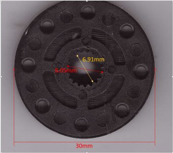
Yes horns are just levers or discs, my first guess would have been an internal spline, it has 18 Teeth

There is standards for Servo Horns, but the servos are Chinese and seem to use a non standard teeth / horn setup, so cant find a great deal of info on it.


Servo Horn 18T.JPG

Regards

DJ
 
It's quite the project if you're coming at it with little experience. Not that that should stop you!

What you'd need to do is create a form broach. Initially, this is the same as cutting a gear, though you need it to be quite long.

Same idea as here, but with a more complex profile:


Lots of ways to make the tool - depends on what you have available?
 
Hi

Thanks for the reply, just realised broaching wouldnt work as that requires the broach to go through the entire piece, for horns this wouldnt work as they are capped so they can be screwed to the end of the servo shaft, so it would have to be done with a tool that did not require to go all the way through the piece.

Regards

DJ
 
I wonder if 3D-printing could be an option.....

At work, a global supplier of fan products sent us some new prototype fans with 3D-printed impellers.
I asked twice just to be sure, and they confirmed it was safe to run them up to 15,000 RPM.
I was surprised, they worked great and did not fly apart at high speeds.

...and this printer had another axis of rotation... the impeller was turning while printing.
Of course that kind of printer is likely beyond budget.... certainly for me.

Brian
 
Hi Brian

I have tried 3D printing them, FDM printers just dont have the accuracy for the small teeth and my Resin printer prints them great but like the plastic ones that came with the servos, just not strong enough to work with the torque requirements the servo horns wear very quickly, thats why metal horns are preferred when working with higher torques.

Regards

DJ
 
Could you use the resin printed one as a pattern to cast aluminum parts?
Brian
 
Hi Brian

That was an idea I had at one point, design the horns and 3d print them, then use the parts for casting metal ones, but the cost of the equipment needed to cast was prohibitive as I am not sure how often I would cast and didnt want to buy the setup just to cast a few servo horns.

Regards

DJ
 
Back
Top