Creating an internal gear for servo horns

Not being really familiar with servo horns I had to look at some images to see what you guys are dealing with and to get an idea of sizes. At first I was thinking about broaching all the way through and then putting on a separate "cap" piece (basically a washer) to close off the one side so it could still be screwed to the shaft. The sizes we're dealing with are pretty small though, so separate parts become tricky.

Then when I was looking at these (just a random company I found online) I see there looks like a small clearance groove inside the bore where the splines end. That's not real hard to do on a lathe with something like an o-ring groove cutter, and then maybe the spline teeth themselves could be broached in singly using the lathe carriage method where an appropriately shaped piece of HSS is held in the toolholder and the carriage run back and forth the same way as a shaper works. On small parts with small features this method works quite well although on larger features where one might have bigger cuts it can be a bit hard on the carriage. Once you figured out the spline pattern a custom indexing plate could set the proper interval fairly quickly.

Just a thought.

-frank
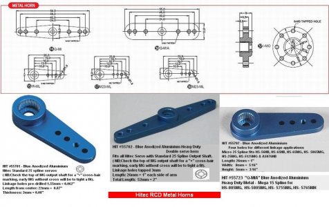

1680117873986.png
 

slow but sure assuming you can index the lathe, can also be done with a dividing head and shaper
you do need to grind your profile to whatever accuracy

how its typically done with a gear shaper (not to be confused with with the normal shaper I mentioned above)
at least at larger sizes, broaching is typical for smaller internal gears
 
Last edited:
Hi Brian

That was an idea I had at one point, design the horns and 3d print them, then use the parts for casting metal ones, but the cost of the equipment needed to cast was prohibitive as I am not sure how often I would cast and didnt want to buy the setup just to cast a few servo horns.

Regards

DJ
If it will be something you only do occasionally, you might want to look at clay pot casting. You can build an "aluminum melter" in an afternoon.
 
@Ice Czar yeah that looks probably what I am looking at, the first video. I have never made my own tools, so would have to look into that and a way to index the head, although I could 3D print a setup for that I think.

@Shotgun due to where I live any casting I do would have to be done indoors so an electric furnace would probably be a solution for me although I would be limited to aluminium and metals with a lower melting temp as I dont think the electric furnaces can do iron or steel.
 
The only way I can make an internal gear/spline is by broaching using a single point broach (one tooth). I would make a detachable cap (brass) to get it mounted. For me this is a lathe job where the chuck is driven by a stepper/servo and used as indexer. I would make a round part for broaching and finish it on the mill. That way it can be hold secure and true in the chuck.
 
@Huub Buis yeah, good thing for me is its only 18 teeth so not a huge job to do one at a time, however I have a few to make. I do have a couple of stepper motors kicking about that I could possibly do something with to setup an indexer, but probably just as quick to 3D print something to do the same job. its the tooling and making that will be an issue for me.
 
If 3D printing is strong enough or holds long enough, I would 3D print these parts. In my bigger lathe I use 3D printed gears. They hold for more than a year now and if they break, the damage is less then when I fit (all ready made) POM gears.

I can CNC broach on the lathe and manually on the mill. Moving small parts to the mill is difficult so I try to do as much of the critical work in one fixation on the lathe and move to the mill for the none critical work.
 
What is your choice of materials? Depending upon material, there are possibilities. Delrin is a reasonably strong material and it would be possible to make the internal splines by pressing a heated mating splined shahaft into an undersized hole. The Delrin will melt and flow up around the splines on the shaft, formiong yout internal splines. I would form the splines first and then use that feature as a reference for the remainder of the machining.
 
@RJSakowski They are either going to be aluminium or steel, depending on the frames I am designing that they will fit into, more than likely aluminium to save a little weight.
 
These servo's can't break steel but maybe aluminum. For ease of machining, I would try POM (Delrin) first and if that isn't strong enough I would make one from aluminum. For POM I don't harden the cutter and make it from mild steel. For aluminum it must be hardened and I would choose silver steel for the cutter. Just grinding this cutter from a HSS bar is also possible. If it's for POM, I wouldn't even grind a relief angle.
 
Back
Top