Enco Bandsaw Repair

7milesup

H-M Supporter - Gold Member
H-M Supporter Gold Member
Joined
Jan 7, 2016
Messages
3,273
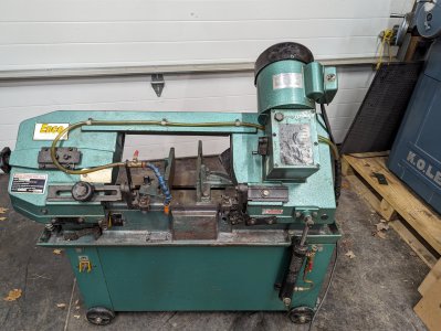
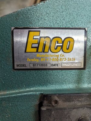
I purchased this Enco bandsaw on an online auction sight unseen. I figured, how bad could it be?

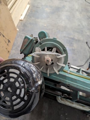
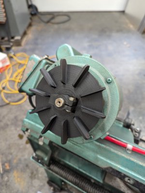
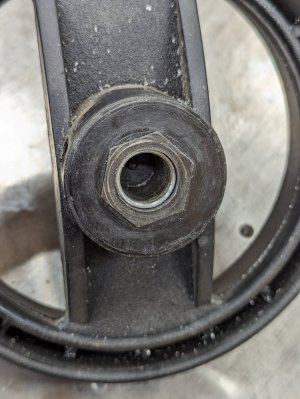
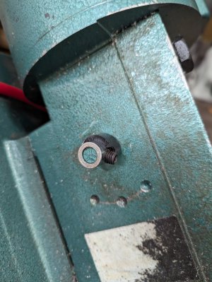
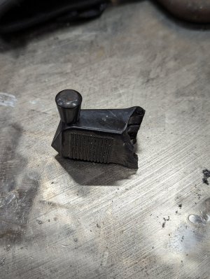
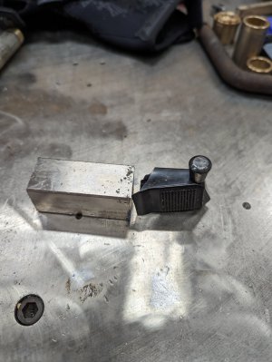
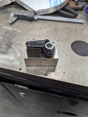
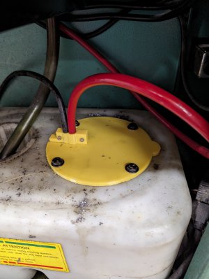
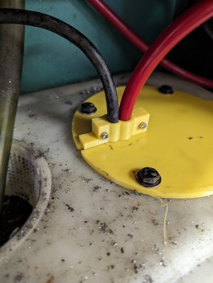
Once home, I grabbed my tractor to unload it from the pickup, utilizing my pallet forks. Unfortunately, it tipped over towards the tractor and pushed the cooling fan shroud into the cooling fan on the bandsaw motor. This was an omen.

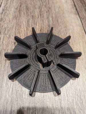
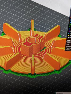
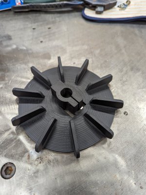
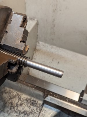
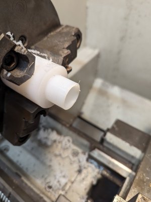
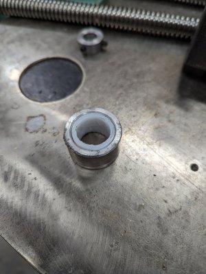
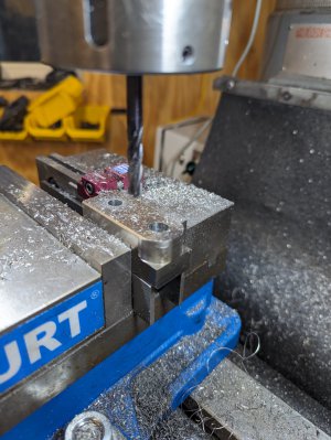
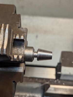
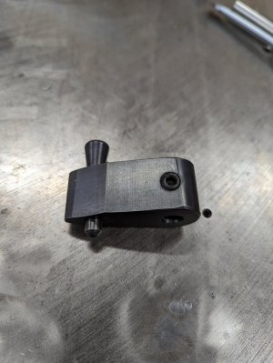
Once I removed the fan shroud and confirmed that the plastic fan was all that was broken (other than my ego), I drew a new fan in Solidworks. That drawing was then sent to my 3D printer, and a few hours later, I had a new fan.
 

Attachments

  • PXL_20231019_005842214.jpg
    PXL_20231019_005842214.jpg
    591.5 KB · Views: 16
  • PXL_20231019_005915476.jpg
    PXL_20231019_005915476.jpg
    619.9 KB · Views: 16
  • PXL_20231019_005952273.jpg
    PXL_20231019_005952273.jpg
    220.3 KB · Views: 13
  • PXL_20231019_012528023.jpg
    PXL_20231019_012528023.jpg
    384.8 KB · Views: 12
  • PXL_20231028_012316085.jpg
    PXL_20231028_012316085.jpg
    361.5 KB · Views: 12
  • PXL_20231028_030808751.jpg
    PXL_20231028_030808751.jpg
    456.4 KB · Views: 12
  • PXL_20231029_150601570.jpg
    PXL_20231029_150601570.jpg
    291.8 KB · Views: 13
  • PXL_20231029_151301023.jpg
    PXL_20231029_151301023.jpg
    202.8 KB · Views: 17
I then discovered that as soon as some pressure was placed on the blade during a cut, the blade would come off the drive pulley. During a close examination of the drive pulley, it appeared that it was worn in such a manner that it might contribute to the blade coming off during a cut. I posted this issue in the “What did you do in your shop today” thread and had several suggestions on how to correct this issue. I decided to do a light clean-up on the pulley to determine if that would correct the issue.
How to hold this pulley in my lathe was another matter. I initially thought I could get the chuck jaws to grip the pulley, but it was a haphazard setup at best. I needed a setup to ensure that the pulley's driveshaft and face were concentric and true. I should point out that when I say the “face” of the pulley, I am referring to the surface that drives the blade. The solution, of course, was to mount the pulley on a shaft and then chuck that up in the lathe. The hole diameter in the pulley is just slightly less than 1”, so I turned a shaft down but left a small shoulder for the pulley to register against. A hole was bored in the end of the shaft and tapped for a ⅜-16 bolt to secure the pulley, but the next step would be on the mill to cut a keyway in the shaft. Back to the lathe, and once all chucked up, I skimmed a little off the “face,” just enough where I felt it would run true.
 

Attachments

  • PXL_20231113_222326551.jpg
    PXL_20231113_222326551.jpg
    284.7 KB · Views: 12
  • PXL_20231113_223346606.jpg
    PXL_20231113_223346606.jpg
    183 KB · Views: 12
Next up for repair was the vise ACME screw. The previous owner apparently wore out the ACME screw and nut because the one that was currently installed was incorrect. The rotation of the vise handwheel operated in reverse. He also had a nut with a bent piece of metal as a spacer and a zip tie to hold it all together. I ordered the correct ACME screw and nut from McMaster. I knew that the vise had a cast iron “nut” that the lead screw ran in, but getting a new one was out of the question. The hand wheel also was very sloppy on the ACME screw, so a thin bushing was turned and pressed into the hand wheel. The hand wheel would be secured with a set screw.
Since I would be using an ACME nut, I needed a spacer, too. Not wanting the ACME screw to rub on the spacer, I turned down some UMHW to act as a sleeve.
 

Attachments

  • PXL_20231229_232257559.jpg
    PXL_20231229_232257559.jpg
    225.7 KB · Views: 8
  • PXL_20231229_232307381.jpg
    PXL_20231229_232307381.jpg
    282.3 KB · Views: 9
  • PXL_20240104_022934003.jpg
    PXL_20240104_022934003.jpg
    265.5 KB · Views: 8
  • PXL_20240104_025329698.jpg
    PXL_20240104_025329698.jpg
    190.9 KB · Views: 8
  • PXL_20240105_233610850.jpg
    PXL_20240105_233610850.jpg
    148.3 KB · Views: 8
  • PXL_20240106_010420551.jpg
    PXL_20240106_010420551.jpg
    258.7 KB · Views: 9
  • PXL_20240105_212921804.jpg
    PXL_20240105_212921804.jpg
    276.1 KB · Views: 9
  • PXL_20240106_010828236.jpg
    PXL_20240106_010828236.jpg
    257.3 KB · Views: 9
The support block for the ACME screw and handwheel was also worn. I removed that support block and bored it out for an Oilite bronze bushing. The ACME screw was turned down, and a stop collar was fabricated to prevent the ACME screw threads from chewing up my bronze bushing. I left enough of a flange on the bronze bushing for the stop collar to ride against it. The recess for the flange on the bushing needed to be slightly larger and deeper. The job was done by a trip to the mill and a quick conversational program utilizing a circle frame. The bronze busing was pressed into the support block and then trimmed in the mill.
A bronze washer was inserted between the hand wheel and the support block.
Once it was all back together, I must say that it is one of the smoothest band saw vise mechanisms I have had the pleasure of operating.
Note: The set screws sat flush once tightened down.
 

Attachments

  • PXL_20231229_232233301.jpg
    PXL_20231229_232233301.jpg
    197.1 KB · Views: 7
  • PXL_20240105_173852398.jpg
    PXL_20240105_173852398.jpg
    222.7 KB · Views: 7
  • PXL_20240105_203429039.jpg
    PXL_20240105_203429039.jpg
    176.4 KB · Views: 7
  • PXL_20240105_211038476.jpg
    PXL_20240105_211038476.jpg
    225.5 KB · Views: 7
  • PXL_20240105_212839715.jpg
    PXL_20240105_212839715.jpg
    255.5 KB · Views: 8
  • PXL_20240105_212926582.jpg
    PXL_20240105_212926582.jpg
    165.5 KB · Views: 7
  • PXL_20240105_213307676.jpg
    PXL_20240105_213307676.jpg
    201.5 KB · Views: 7
  • PXL_20240105_213535625.jpg
    PXL_20240105_213535625.jpg
    158.9 KB · Views: 6
  • PXL_20240106_023503329.jpg
    PXL_20240106_023503329.jpg
    199.3 KB · Views: 7
  • PXL_20240106_023721942.jpg
    PXL_20240106_023721942.jpg
    218.3 KB · Views: 7
The next issue to correct was the gear shift selector. When I tried to move the lever, it literally fell apart in my hands. It mainly consisted of plastic with a metal sleeve that slipped over the gearbox shaft and a spring-loaded registration pin to keep the lever from moving out of the selected gear.
I started by cutting a 1”x1” blank to length. Then, over to the mill to bore the hole for the gear shift shaft and the registration pin. The block was also counterbored where the registration pin would reside. The end of the lever was rounded off while it was in the mill using my conversational programming on the Trak (Sharp) mill. A quick comparison to the old lever showed that I was on track. Back to the mill to finalize the shape and then to the surface grinder to remove the milling marks. I will admit that I did not spend much (any) time on the surface grinder setup, so some of it looks a little janky.
The registration pin was a bit of a challenge because I could not get the old pin out and ended up destroying it, but I managed to save the spring and get some measurements. A new registration pin was turned in the lathe and threaded on one end. The “pull” needed to be turned separately, along with boring and tapping it for threads. The taper on the pull was done with the compound and a “looks about right” method. All of the parts were oil-quenched to achieve the color. The spring was placed over the pin, which was inserted into the shift lever, and then the pull screwed on and secured with some Loctite.
I heated the parts with a propane torch and quenched them in oil to give it the dark finish I sought. I'm not sure how it will hold up, but if it is an issue, it will be easy enough to do over.
I neglected to take pictures of the registration pin before I assembled it. Oops.
 

Attachments

  • PXL_20231230_172754743.jpg
    PXL_20231230_172754743.jpg
    316.2 KB · Views: 8
  • PXL_20231230_172813524.jpg
    PXL_20231230_172813524.jpg
    360.9 KB · Views: 7
  • PXL_20231230_173041738.jpg
    PXL_20231230_173041738.jpg
    257.7 KB · Views: 7
  • PXL_20231230_191357302.jpg
    PXL_20231230_191357302.jpg
    189 KB · Views: 8
  • PXL_20231230_214927645.jpg
    PXL_20231230_214927645.jpg
    307.8 KB · Views: 8
  • PXL_20231230_215513072.jpg
    PXL_20231230_215513072.jpg
    302.9 KB · Views: 8
  • PXL_20231230_215826086.jpg
    PXL_20231230_215826086.jpg
    372.2 KB · Views: 8
  • PXL_20231230_223944111.jpg
    PXL_20231230_223944111.jpg
    285.1 KB · Views: 8
  • PXL_20231231_165214538.jpg
    PXL_20231231_165214538.jpg
    212.2 KB · Views: 8
  • PXL_20231231_210606887.jpg
    PXL_20231231_210606887.jpg
    170.1 KB · Views: 9
  • PXL_20231231_210724736.jpg
    PXL_20231231_210724736.jpg
    361 KB · Views: 7
  • PXL_20231231_212851422.jpg
    PXL_20231231_212851422.jpg
    186.1 KB · Views: 7
  • PXL_20240101_025550539.jpg
    PXL_20240101_025550539.jpg
    153.9 KB · Views: 8
  • PXL_20240105_173834827.jpg
    PXL_20240105_173834827.jpg
    244.2 KB · Views: 7
The last issue I decided to tackle was the cover for the coolant tank. The original metal cover was just sitting on top, but there were several gaps, including an area that the original owner had cut out of the coolant tank so he could get the pump in. I decided to design a new cover in Solidworks and 3D print it. It turned out well, with integrated clamps for the power and coolant lines going to the pump.
I need to design a similar system for the drain opening.
 

Attachments

  • PXL_20240223_154355558.jpg
    PXL_20240223_154355558.jpg
    209.8 KB · Views: 6
  • PXL_20240223_154400532.jpg
    PXL_20240223_154400532.jpg
    187.8 KB · Views: 6
I should have mentioned that the purchase price of this thing was just a few dollars shy of $400, including auction fees and taxes. So, even though I spent a fair amount of time repairing it, in the end, I am quite happy with how it turned out. :)
 
Nice design; motor direct to gearbox. How many speeds is it?
 
Back
Top