- Joined
- Nov 16, 2012
- Messages
- 5,596
Hi Folks...
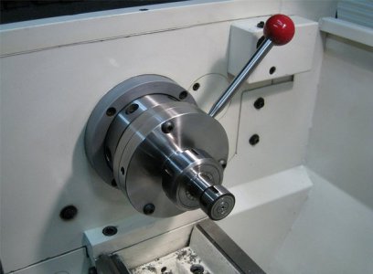
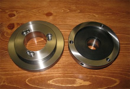
Someone in our group requested that I mount an ER40 chuck to a D1-4 lathe backplate. No problem, we can do that... Here's how.
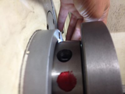
First, the backplate was brand new and in almost all cases, the tapered hole is cut undersized. I've seen this on every new backplate I've ever encountered. To check, mount the backplate on the spindle, fasten it firmly and use a flashlight from behind to look for light at the spindle interface. It shows quite clearly in the following photo. The interface must fit flat and simultaneously, the nose taper must engage the hole taper for proper alignment.
There's about 1.5 thousandths inch of light leaking through that gap between the interfaces (look at the top between the spindle and plate).
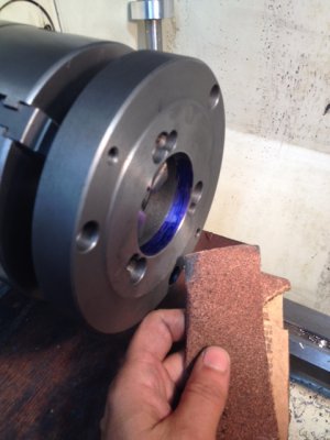
Things need to be fixed. It won't take much reduction on that taper to allow the interface to seat properly so, the plate was mounted on a chuck and coarse sandpaper was used to open-up the tapered hole. There is trial and error here and you don't want to take too much off (although that can be fixed if you screw-up by taking off a small amount from the flat part of the interface).
Note that I'm using a simple 3J chuck to hold the plate from the straight part of the hole. No fancy alignment is needed here. Take a very, very light skim pass over the flat interface. This just makes sure it's flat.
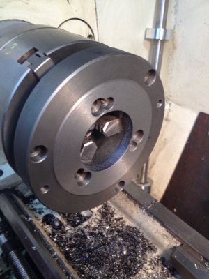
WORD OF CAUTION: To do this, you and the rest of your body are very near a spinning chuck. NO long sleeves. ONE hand holding the sandpaper. OTHER hand near the kill switch. Get it? The hole was marked with ink and sandpaper was used with the plate running at/about 300 RPM. As soon as all of the ink is gone, I know from experience that removes about 0.0005" of material (because the ink soaks in a little bit). It took about 4 tries of doing this before a very slight zero-tolerance fit was obtained. This is tested by removing the working chuck, installing the lugs in the plate and snugging them tightly to attach the backplate.
Remember, upon using firm pressure when tightening the camlocks, the flat interfaces must simultaneously meet as the tapered surfaces engage. It's a very snug interference fit and when you release the camlocks, the backplate should pop off.
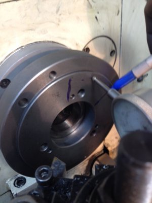
Once this is done, now we know the interface is flat and the taper is fitting perfectly. This must be verified... Put an indicator against the surface as shown, spin the plate by hand and mark the locations of any high spot (one will certainly exist). Next, unlock the backplate and re-mount it by rotating the lug position one set of holes so it's offset 120 degrees. Put the indicator back on the surface and verify that the high spot is in the same place as the previous markings. Repeat this for one more 120 degree re-mounting. The high spot should always show in the same place. This verifies that the interface and taper are locking-up consistently.
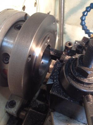
We're ready to rock & roll... Now go ahead and make everything "square" by truing-up the faces and cleaning-up the center hole as shown. Also, in this case, a shoulder is needed to fit the boss in the back of the ER chuck. In this particular case, the ER chuck must fit tightly on the shoulder. This requires sneaking-up on the final size. -Don't blow it! Get close and use emery cloth wrapped around a tool blank until the chuck fits with a very slight friction fit. For normal chucks, I don't do it this way but because of how the bolts attach in this case, it must be done this way. -And you'll see later, it caused a problem (as it always does)...
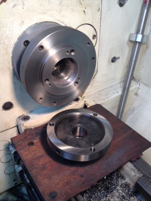
Here's the straight hole getting cleaned-up as well as an overall view of the nicely squared-up backplate. Remember to break all the edges or you'll be bleeding every time you use your lathe...
The fun part is over now and we're down to drilling holes and counter sinking (yawn!).
Use ink to mark the locations of the intended holes.
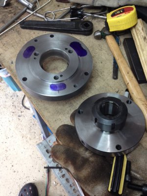
Grab a trusty piece of scrap, turn it to the diameter of the threaded holes and put a point on it. Carefully line-up the ER chuck to the desired location and mark where the holes will go.
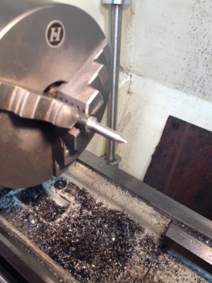
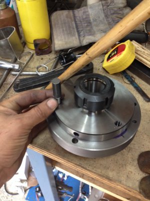
Drill the holes (not shown) and countersink from the correct side (don't mess that up or you'll be crying).
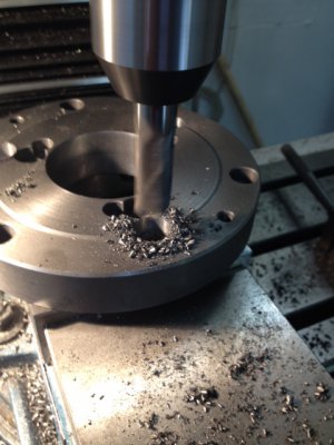
And this is what it should look like now...
As you see, the countersunk bolt heads are on the backside of the plate -and this is why we need that tight fitting shoulder to align the chuck... because you can't tighten the bolts while the plate is attached to the spindle. We have no way to align the ER chuck manually and must rely on the shoulder.
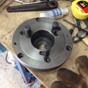
... And of course, as predicted... when mounted perfectly on the should, the taper has 1.5 thou runout!
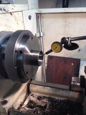
Uh-Oh, what now boss? What do we do?
Well, as expected, every place I check on the backplate, it's perfect. DI needle does not move except for background vibration.
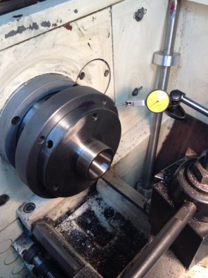
Hmmm, boss man says something's wrong with the chuck...
YEP... When checking the thickness as shown in 3 different places, it varies by 0.002". That could certainly account for some error at the spindle because, it's not sitting flat. Other things could be wrong too -such as overall concentricity between the chucks shoulder boss and the tapered hole...
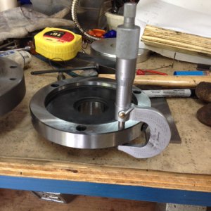
OK, now what? First, this ER chuck belongs to someone else. -And there's no way in the world anyone is going to let me machine it. Furthermore, I have a candle's chance in a windstorm of ever fixturing it up well enough to machine it properly... Not only that, I can tell by looking at the piece that it's about Rockwell 40 C. And light cuts don't come out well on moderately hard metal...
Answer? Emery cloth... Get to know it and get to like it. Instead of messing-up the customer's chuck, I manually tweaked the mating surface near the shoulder of the backplate. Took a little elbow grease and 2 hours, 20 minutes (start to finish) but guess what?
Runout is +/- 0.0004".

BTW, the various OD's on the of the chuck itself show some runout... but who cares? All that matters is the ER taper. FWIW, when measuring a taper like this, you need to check at the inner and outer hole of the taper. Mark the high spot and make sure they coincide. If they don't the machined ER taper is bad. In this case the RO was consistent.
... Anyhow, on that ER chuck, there are two places where I can verify out-of-concentric dimensions greater of about 0.002 to 0.003" inch. No worries, it all came out in the wash anyhow... This just shows you can't throw your arms up in the air and say it's junk... We all aspire to be machinists -and figuring things out and fixing stuff like this is what machinists do for a living.
Ray


Someone in our group requested that I mount an ER40 chuck to a D1-4 lathe backplate. No problem, we can do that... Here's how.
First, the backplate was brand new and in almost all cases, the tapered hole is cut undersized. I've seen this on every new backplate I've ever encountered. To check, mount the backplate on the spindle, fasten it firmly and use a flashlight from behind to look for light at the spindle interface. It shows quite clearly in the following photo. The interface must fit flat and simultaneously, the nose taper must engage the hole taper for proper alignment.
There's about 1.5 thousandths inch of light leaking through that gap between the interfaces (look at the top between the spindle and plate).

Things need to be fixed. It won't take much reduction on that taper to allow the interface to seat properly so, the plate was mounted on a chuck and coarse sandpaper was used to open-up the tapered hole. There is trial and error here and you don't want to take too much off (although that can be fixed if you screw-up by taking off a small amount from the flat part of the interface).
Note that I'm using a simple 3J chuck to hold the plate from the straight part of the hole. No fancy alignment is needed here. Take a very, very light skim pass over the flat interface. This just makes sure it's flat.

WORD OF CAUTION: To do this, you and the rest of your body are very near a spinning chuck. NO long sleeves. ONE hand holding the sandpaper. OTHER hand near the kill switch. Get it? The hole was marked with ink and sandpaper was used with the plate running at/about 300 RPM. As soon as all of the ink is gone, I know from experience that removes about 0.0005" of material (because the ink soaks in a little bit). It took about 4 tries of doing this before a very slight zero-tolerance fit was obtained. This is tested by removing the working chuck, installing the lugs in the plate and snugging them tightly to attach the backplate.
Remember, upon using firm pressure when tightening the camlocks, the flat interfaces must simultaneously meet as the tapered surfaces engage. It's a very snug interference fit and when you release the camlocks, the backplate should pop off.

Once this is done, now we know the interface is flat and the taper is fitting perfectly. This must be verified... Put an indicator against the surface as shown, spin the plate by hand and mark the locations of any high spot (one will certainly exist). Next, unlock the backplate and re-mount it by rotating the lug position one set of holes so it's offset 120 degrees. Put the indicator back on the surface and verify that the high spot is in the same place as the previous markings. Repeat this for one more 120 degree re-mounting. The high spot should always show in the same place. This verifies that the interface and taper are locking-up consistently.

We're ready to rock & roll... Now go ahead and make everything "square" by truing-up the faces and cleaning-up the center hole as shown. Also, in this case, a shoulder is needed to fit the boss in the back of the ER chuck. In this particular case, the ER chuck must fit tightly on the shoulder. This requires sneaking-up on the final size. -Don't blow it! Get close and use emery cloth wrapped around a tool blank until the chuck fits with a very slight friction fit. For normal chucks, I don't do it this way but because of how the bolts attach in this case, it must be done this way. -And you'll see later, it caused a problem (as it always does)...
Here's the straight hole getting cleaned-up as well as an overall view of the nicely squared-up backplate. Remember to break all the edges or you'll be bleeding every time you use your lathe...


The fun part is over now and we're down to drilling holes and counter sinking (yawn!).
Use ink to mark the locations of the intended holes.

Grab a trusty piece of scrap, turn it to the diameter of the threaded holes and put a point on it. Carefully line-up the ER chuck to the desired location and mark where the holes will go.


Drill the holes (not shown) and countersink from the correct side (don't mess that up or you'll be crying).

And this is what it should look like now...
As you see, the countersunk bolt heads are on the backside of the plate -and this is why we need that tight fitting shoulder to align the chuck... because you can't tighten the bolts while the plate is attached to the spindle. We have no way to align the ER chuck manually and must rely on the shoulder.

... And of course, as predicted... when mounted perfectly on the should, the taper has 1.5 thou runout!

Uh-Oh, what now boss? What do we do?
Well, as expected, every place I check on the backplate, it's perfect. DI needle does not move except for background vibration.

Hmmm, boss man says something's wrong with the chuck...
YEP... When checking the thickness as shown in 3 different places, it varies by 0.002". That could certainly account for some error at the spindle because, it's not sitting flat. Other things could be wrong too -such as overall concentricity between the chucks shoulder boss and the tapered hole...

OK, now what? First, this ER chuck belongs to someone else. -And there's no way in the world anyone is going to let me machine it. Furthermore, I have a candle's chance in a windstorm of ever fixturing it up well enough to machine it properly... Not only that, I can tell by looking at the piece that it's about Rockwell 40 C. And light cuts don't come out well on moderately hard metal...
Answer? Emery cloth... Get to know it and get to like it. Instead of messing-up the customer's chuck, I manually tweaked the mating surface near the shoulder of the backplate. Took a little elbow grease and 2 hours, 20 minutes (start to finish) but guess what?
Runout is +/- 0.0004".

BTW, the various OD's on the of the chuck itself show some runout... but who cares? All that matters is the ER taper. FWIW, when measuring a taper like this, you need to check at the inner and outer hole of the taper. Mark the high spot and make sure they coincide. If they don't the machined ER taper is bad. In this case the RO was consistent.
... Anyhow, on that ER chuck, there are two places where I can verify out-of-concentric dimensions greater of about 0.002 to 0.003" inch. No worries, it all came out in the wash anyhow... This just shows you can't throw your arms up in the air and say it's junk... We all aspire to be machinists -and figuring things out and fixing stuff like this is what machinists do for a living.
Ray


