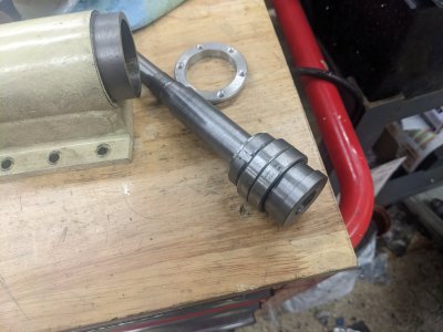
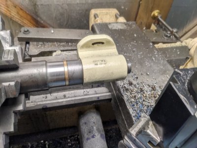
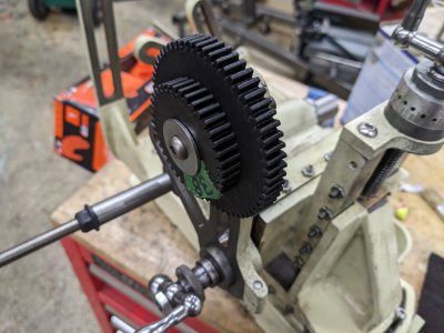
So the list of things to complete is pretty short now!
1-I have to do the linkage from the hob spindle to the work spindle (which the above parts do the start of).
2- I have to make the work-holding and hob holding MT2 adapters. There will be a challenge there, as I have to make the work holding spindle particularly long (thanks to not doing the CAT20 holder, I ended up not 'wasting' as much room)
3- Mounting the electric motor
4- Figuring out how to drive the motor. It is a 12V 337W motor that I'd like to have with a variable power supply, but finding one is going to be a touch troublesome.
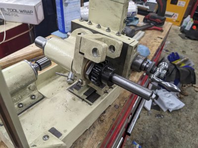
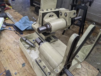
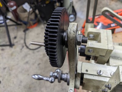
SO, lets continue on #1. There are a pair of universal joints that move the power from the big "L" shaped piece to the work-spindle. On one side, the arm holds the gear (at the L) and the other, transfers to the worm gear (which is the 20-1 reduction).
First, I wanted to get the Universal Joint "centers" done. This was a bit of an arbitrary choice, but makes the assembling of them as I go along possible.
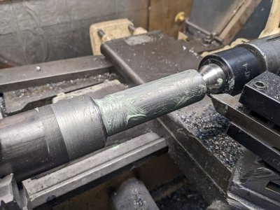
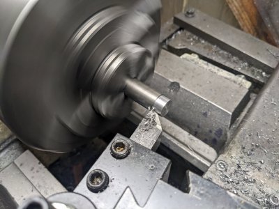
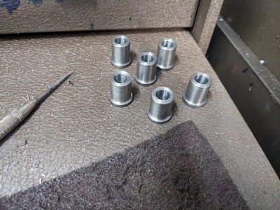
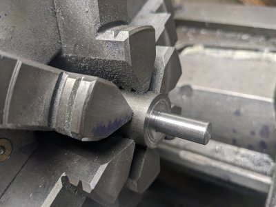
I started with a 1.5" piece of 12L14, turned the outside down a touch, and turned the inside to 1.125" long enough to make both of these:
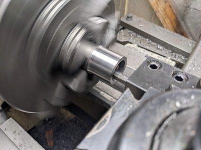
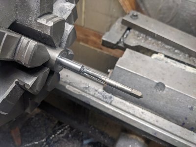
After that, I drilled/tapped the set-screw holes holes at 90 degrees (4 of them!) that act as the pivots for the universal joint.:
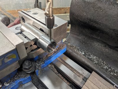
I drilled all the way through at each side, and used a square to line up the opposite side for the cross drilling, I believe I'm pretty darn close to perfect.
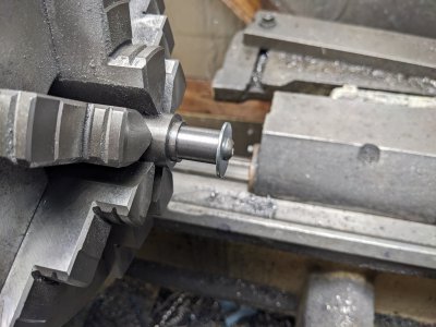
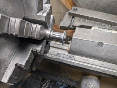
Finally, I parted it off:
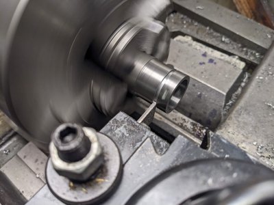
I repeated the drilling/tapping/parting to get a 2nd one out of it, then used the surface grinder to get them down to thickness. I managed to not get a picture of that part

After some deburring, they are done, though THAT picture is missing too.
After that, I decided to start on the worm-gear side.
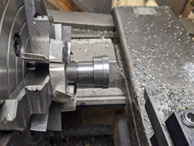
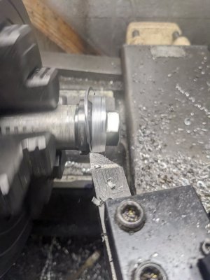
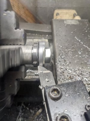
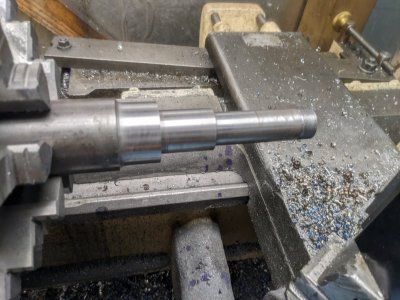
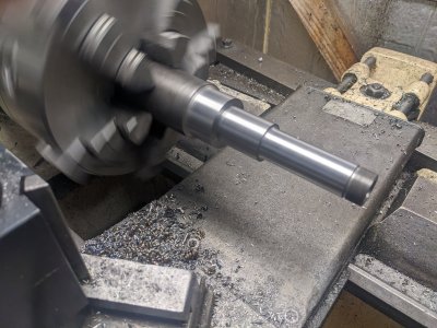
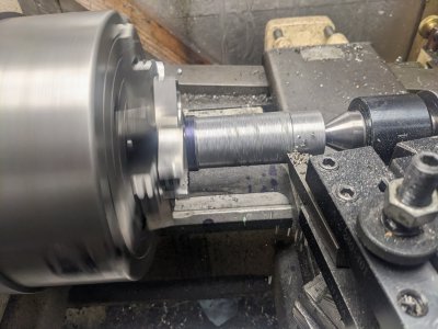
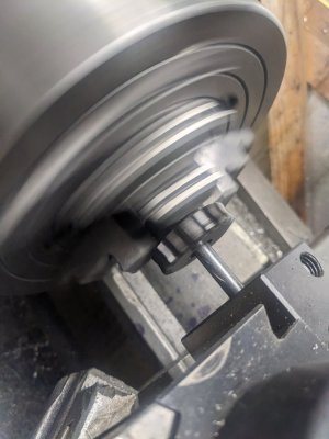
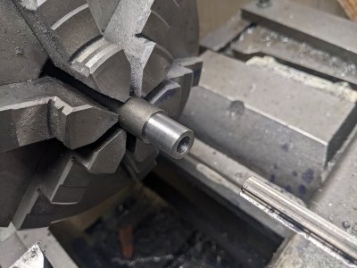
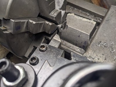
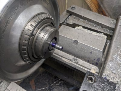
I started by turning it down to be a fit into the bracket it is going to ride in:
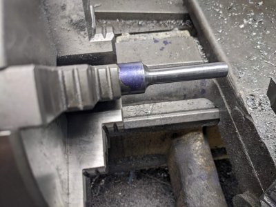
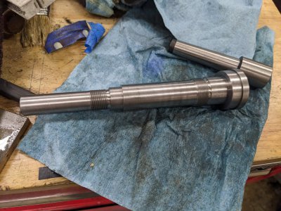
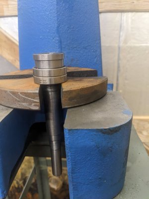
And you can see how it goes through here:
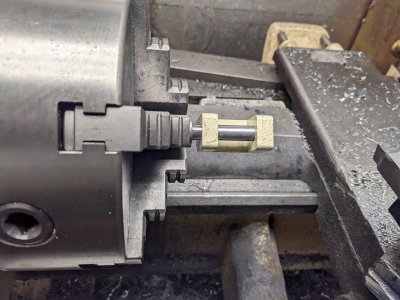
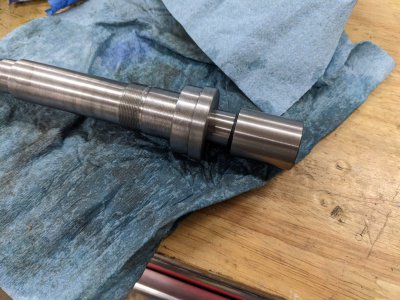
The worm gear rides in the center of that, and there is a set screw on a 2nd collar that holds it all in place (perhaps tomorrow's task!).
After getting that end finished, I flipped it around and started forming the Universal joint side:
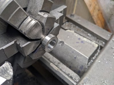
It looks a litlte weird, but what I did was turn and face it, then drilled it out with my largest drill bit, then went in with the 5/8" endmill in the tailstock to get it about the right size. In retrospect thats perhaps not the perfect idea, but it was nice to get that much material removed.
The worm gear is held from rotating with a key, so I cut that next. This poor 1/8" endmill has received a ton of abuse during this project, and managed at least 1 more, though I think it is getting dull (it wondered for the first time)! Either way, the keyway turned out good enough, particularly given how tight the gear is on the shaft.
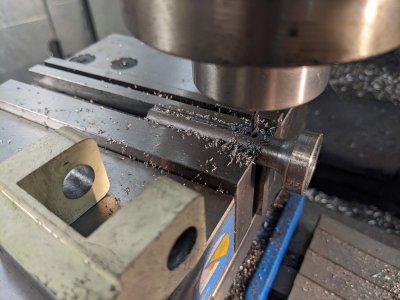
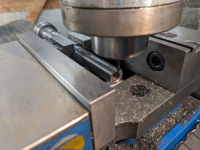
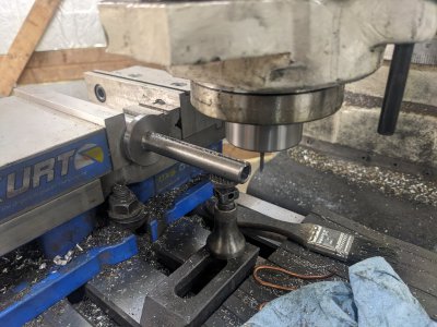
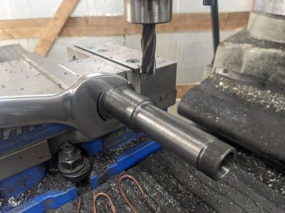
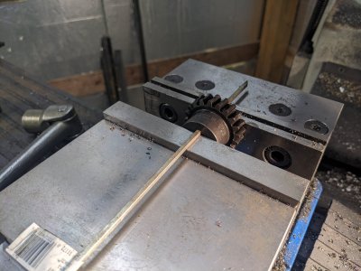
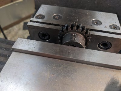
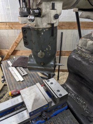
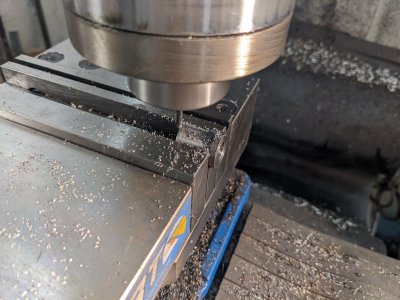
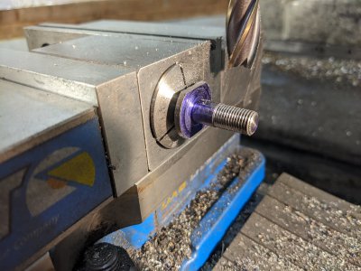
Next, I needed to form the 'fork' end. This was mostly just trying stuff to see how it would work out (I didn't spend much time planning this part!). First I did top-and-bottom with my 5/8" mill:
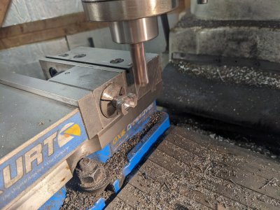
In retrospect, I probably could have increased stick out and done this with side milling, but I didn't think about it. Additionally, I needed it in this orientation for the next step, which is to better square up the 'insides' of the fork:
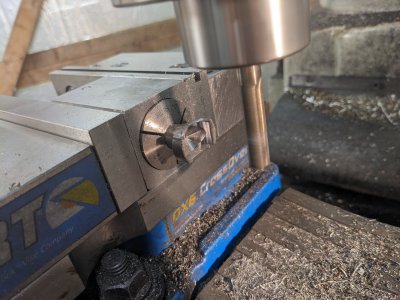
I suspect this is to prevent the forks from hitting each other (indeed, it says to spend some time with some files to round things over to keep it running smoothly, so I figure I'll be doing that anyway).
Finally, I used a center drill to make a sizable intent on each side for the grub-screws from the hoop to hit, and use as the pivot points:
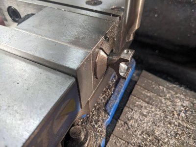
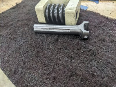
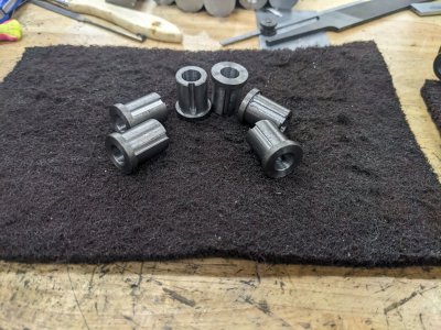
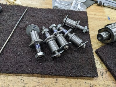
After a few minutes on the knock-off scotchbrite wheel, here it is, next to the parts it'll end up keeping together!
