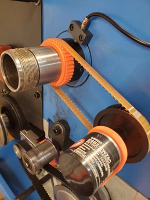
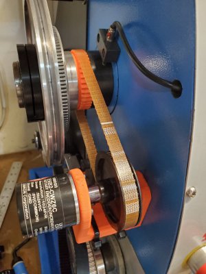
Has anyone installed Clough42's electronic leadscrew on a PM machine?

A broach set sounds nice. But cutting a broach on something close to a 2" ID seems fairly scary. And pretty expensive.

Al least it's aluminum. I should be able to do most of the keyway material removal on my PrintNC mill with an 1/8" bit. It will leave round corners and I can square them up with a hand file if nothing else.
You would need to make your own bushing to guide the broach.

Like I said earlier, I reused existing parts and adapted the timing pulley to work with my intermediate shaft. Since the pulley was relatively small, my broach set worked with the supplied bushings.
 
It was from another person on here- not sure if they want to make more or not, so I will contact and see.

the servo on mine fit under the ways with no issues, although plugging everything in took a few minutes. I 3D printed mounts.
 
I had initially tried the same thing and had the same result as you. Knowing it is a module 1.5 gear I decided to get a 60 tooth plastic gear from Grizzly for a G0602 and then run 60 to 40 GT2 belt for my encoder. I figured the plastic gear with the little load that's on it would need minimal lubrication and probably run quieter. The gear from grizzly does fit directly to the PM gear parts. I think the ultimate thing to do would be to put a belt pulley on the spindle. The way it is now I can switch back to the geartrain if the need arose. I like your install of the servo motor. On my 1130v fitting where you did was a no go, wasnt even close to fitting between the motor and bed. My second plan was the 5:1 worm gearbox which works but seems to add enough extra drag that the servo has a hard time turning the gearbox. I will likely switch to your servo mounting when I have time to space the motor farther away from the bed
I ended up with four 1.5mm washers to extend each motor mount spacer. That's plenty to make it fit w/o problems and a good mounting solution (IMHO). However, any adjustment for belt tension is extremely limited. Perhaps a mm in each direction. And the distance between the gearbox and the servo shafts is such that the result from the SDP-SI calculator is a 114 tooth pulley....which is about the only belt they don't sell. So, I suspect I'm going to need to mount an idler to allow adjusting tension. The other option would be to use a 24 grove pulley for the servo and a 72 for the gearbox. Still 3 to 1 ratio, but the belt is a bit longer and all of the lengths that might be needed are available. However, the lower stud that the gear cover goes on could end up being an obstacle for the 24/72 combo.

One more comment. I was dreading the removal and reinstall of the motor...but it was much easier than expected. I did it once for 3 washers....and then again to add one more. Maybe 90 minutes on the first try, 60 on the second.
 
Last edited:
If you go back to the pic of my install I removed the lower stud and used a piece of 3" channel iron to jog around my servo. I have pulleys here to do a 6:1 belt so hopefully I can get a belt that will work. I think it was post #88 on page 9
 
I decided to try a 3d printed spindle gear to fit a T5 timing belt.

It was easy to find parametric code for T5 gear generation. Problem was that the code was written for openSCAD. Which I don't know. So I downloaded the CAD program and the gear generator. It was quite easy to modify the program to generate the gear that I needed. Their example had 8 teeth, I increased it to 40 teeth. They had a flange (retainer) which I set to zero and turned off. At this point, it was almost what I wanted. I still needed to add a keyway. And increase the thickness by 3mm. Time to move it over to Fusion 360.

But unfortunately, there's not a common format between the two pieces of software. There's some talk about using FreeCAD to bridge between them.....but that's starting to get too darn complicated. Instead, I found that adding a "projection" statement at the top of "main" allows changing the output of the SCAD stuff from 3D down to 2D (a dxf file). Once I had a dxf, Fusion could extrude the gear splines 12mm, extrude a non-splined 3mm spacing section, and add the keyway.

I switched back to a .4mm nozzle in my 3d printer and printed the piece. Initially too tight on the bore (ID), so I sanded the interior lightly and got it to fit.
20231224_152701.jpg20231224_155649.jpg

I may reprint this part with two tiny changes. First, make the bore a bit bigger and eliminate the "sand to fit" step. Second, there's no reason not to make the toothed area the full 15mm width. It seems to run smoothly and true on the gears w/o any tendency to run off either end....but it can't hurt to have the extra 3mm of width on the gear.

Contrary to my earlier concerns about durability, I now think this plastic gear should last many years.
 
I decided to try a 3d printed spindle gear to fit a T5 timing belt.

It was easy to find parametric code for T5 gear generation. Problem was that the code was written for openSCAD. Which I don't know. So I downloaded the CAD program and the gear generator. It was quite easy to modify the program to generate the gear that I needed. Their example had 8 teeth, I increased it to 40 teeth. They had a flange (retainer) which I set to zero and turned off. At this point, it was almost what I wanted. I still needed to add a keyway. And increase the thickness by 3mm. Time to move it over to Fusion 360.

But unfortunately, there's not a common format between the two pieces of software. There's some talk about using FreeCAD to bridge between them.....but that's starting to get too darn complicated. Instead, I found that adding a "projection" statement at the top of "main" allows changing the output of the SCAD stuff from 3D down to 2D (a dxf file). Once I had a dxf, Fusion could extrude the gear splines 12mm, extrude a non-splined 3mm spacing section, and add the keyway.

I switched back to a .4mm nozzle in my 3d printer and printed the piece. Initially too tight on the bore (ID), so I sanded the interior lightly and got it to fit.
View attachment 471874View attachment 471876

I may reprint this part with two tiny changes. First, make the bore a bit bigger and eliminate the "sand to fit" step. Second, there's no reason not to make the toothed area the full 15mm width. It seems to run smoothly and true on the gears w/o any tendency to run off either end....but it can't hurt to have the extra 3mm of width on the gear.

Contrary to my earlier concerns about durability, I now think this plastic gear should last many years.
Nice work. The gear will probably last decades if not subjected to things like ozone.
 
I'm late to this thread since I have a G0709 but...

I'm considering adding an ELS to my 1030. Any idea if you can get below 8TPI threading?

Here is my PR not only adding a lot more thread pitches, but also changes to support pitches that are not available at all in the original like 1.25mm, by changing the denominator by a factor of 10:


I've used that along with kwackers' thread-to-shoulder branch on my G0709.


More at:

Out of curiosity, those using the same servo as James, what ‘stiffness’ setting did you end up with? With the ‘11’ default installed, it would make noise. I lowered to 8 or 9 and it is silent.

I'm using a 1.5 module 11-tooth gear printed in PETG to drive the 66-tooth change gear from my G0709, and the PETG dampened it and let me use a stiff setting. I no longer remember for sure if I set it to 11 or even stiffer but I didn't have to back down to a really soft setting once I was driving it that way.
 
Out of curiosity, those using the same servo as James, what ‘stiffness’ setting did you end up with? With the ‘11’ default installed, it would make noise. I lowered to 8 or 9 and it is silent.

Edit: belt is loose in photo, that is why it appears not aligned. I made a mistake on the outer encoder mount, so I had to reprint and didn’t have any of the CF PET. That is why the different colour. There is a bearing on the inner mount and all the force is on that bearing- just the flexible drive to the encoder transferring the motion.
Mine came programmed to a stiffness of 12. It tripped off just sitting there, so I lowered it to 11. It seems to work, but it is noisy. If I can snake the RS232 cable into position, I will lower it and see if I can eliminate the noise. I think that it's also possible to lower the stiffness just by changing the dip switches on the end of the servo...maybe with a probe and a mirror.
 
There might be another fix for a noisy stepper. I'm looking at loading a different branch of the code that enables
  1. Setting metric pitch using three decimal places (allowing a much wider range of threading)
  2. Semi-automatic threading to a shoulder
  3. Showing the angular position of the spindle.
Steve Ward wrote the code at https://github.com/kwackers/electronic-leadscrew
A good description of the way the code works is at: https://github.com/clough42/electronic-leadscrew/issues/231

I noticed in his config.h file, the following comment and parameter. Not sure when and if this helps, but thought it was worth a mention.
//================================================================================
// backlash value
// This fixes an issue (which may only apply to me) in that the encoder at certain
// positions 'dithered' causing the stepper to 'vibrate' resulting in noise when the
// lathe was stopped.
// This value effectively adds backlash to the system so that the minimum number of
// steps have to be issued before the motor will move
// set to zero if not required.
//================================================================================


#define backlash 2
 
Back
Top