Has anyone installed Clough42's electronic leadscrew on a PM machine?

Buy the 10 mm one, bore it out like you said and cut a new keyway. I'm in the process of doing that myself. I just made a tool yesterday to cut the keyway. Here is a couple links of how others have done it. Mine is simple, more like Blondihacks.


You shamed me into doing the keyway. It didn't turn out very precise because my tool grinding sucked. It's tough to hold a tool that can't be more than about 13mm long. But, I got it done and my imprecision in oversizing seems to have not created any issues. Perhaps the set screw that bears on the key way slot compensates. Someday I should get a good grinder setup and make a proper tool.

In any event, the pulley is now mounted and my servo mount is also in place. Belt is supposed to arrive in a couple of days along with the pulley and belt for the encoder. I only have about 1mm in either direction for adjustment, so I hope the belt calculator at SDP-SI is correct.
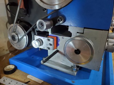
servo_mounted_for_ELS.jpg
 
Mine had the right bore but came with a 6 mm keyway, I needed a 5 mm keyway. One of mine didn't turn out just right either, the second one turned out just about perfect.
 
Out of curiosity, those using the same servo as James, what ‘stiffness’ setting did you end up with? With the ‘11’ default installed, it would make noise. I lowered to 8 or 9 and it is silent.

Edit: belt is loose in photo, that is why it appears not aligned. I made a mistake on the outer encoder mount, so I had to reprint and didn’t have any of the CF PET. That is why the different colour. There is a bearing on the inner mount and all the force is on that bearing- just the flexible drive to the encoder transferring the motion.
I have the same servo and it is incredibly loud. I feel at all times it’s making noise. I may have to try the same thing.
 
I'm getting close to hooking up my wiring.

I'm using the ISV57T (same servo that everyone seems to be using). Was trying to see how many wires I need to run to the servo. I've got something with 12 awg for power and ground. But the controls don't match up.

On the ELS Boost card there are 6 pins:
  1. ALM -
  2. ALM +
  3. EN -
  4. DR -
  5. STP -
  6. +
On the ISV57T, there are also 6 pins.
  1. ALM -
  2. ALM +
  3. DIR -
  4. DIR +
  5. PUL -
  6. PUL +
My guess:
ALM - and ALM + are easy and connect to each other since the names exactly match.​
EN - on the ELS boost ----------> is NC (not connected to anything). there's no related input name on the servo.​
DR - on the ELS boost-----------> DIR - on the servo.​
STP - on the ELS boost ----------> PUL - on the servo.​
+ on the ELS boost --------------> DIR + and to PUL + on the servo.​

I'm hoping someone can tell me if my assumed connections will work. Looks like a minimum of 5 wires are needed.

RR
 
Yes, that sounds right. DIR/STP+ connect together and to the + line on the boost board. If you had an enable line, you could also connect that + there.

The boost board is labeled to match "normal" stepper driver signals. Enable, Step, Direction. Servo controllers tend to be similar, so that should be fine. These are low current control signals, so they are not likely to cause issues should they be connected improperly. The drivers for higher voltage motors tend to also be opto-isolated, creating another layer of protection.
 
Got my belts and my 40 tooth T gear for the encoder. I ordered a 100% plastic (acetal aka delrin) gear for the encoder. Wanted to keep it light to avoid stressing the encoder bearings and figured plastic would be fine since the load is trivial.

The hub ID is 10mm. I was planning to turn a steel shaft and expected a set screw. But, I neglected to notice that the plastic gear has no mechanism for attaching the hub to the shaft. No keyway, no set screw.

Since the ID is only 10 mm, I'm dubious that I can cut a key way using a boring bar and a cutter mounted in it. Not much room. But the gear/hub is only 22mm thick. Seems like I might be able to grind a HSS tool that would mount directly in the toolpost and broach the hub bore while moving toward the spindle? It wouldn't be a very strong/rigid arrangement with 22 mm of stick out, but plastic should cut with very little force.

Other options include adding a set screw directly threaded into the plastic....or using an insert (heat-set or otherwise). The OD of the hub area is 18mm, so there's only 4 mm of material. It looks like a dubiously small area.

I could drill thru both sides of the hub and insert a roll pin (or cotter pin) thru it and the shaft.

Acetal isn't a great candidate for gluing. There's some locktite stuff, but it doesn't talk about bonding to metals with it.
 
My encoder doesn't have a keyway, it has a flat on the 6 mm shaft. I bought an aluminum pulley, 40 tooth, 15 mm wide with 6 mm bore. I turned the hub off of it, then drilled and tapped through the pulley teeth for a set screw.

Once you make for spacer for the shaft and have it installed in the pulley you should be able to do the same.
 
Great point - the stepper is locked "in step" with the spindle via the encoder. The encoder ought to be connected to the spindle via a cog belt such as HTD-3M or similar so that the spindle and encoder always stay in sync.

In addition I think you will find that the "gear" on the spindle itself that meshes with the change gears is a T5 pitch so you can add a T5 pitch pulley to the encoder and drive it direct with a belt.
I went down the path of trying to use the spindle gear directly. Bought a T5 belt and T5 40 tooth pulley. Got everything in place this morning and noticed the belt occasionally did a little "hump" movement. And then I realized, the spindle gear must not be T5. It's close, but not close enough. A picture makes this very clear.

Spindle_gear.jpg


This is on a PM-1130v. Does anyone know what tooth pattern is used on the spindle gear for my lathe? It definitely doesn't mesh properly with a T5 belt. I'm guessing that it may not mesh with any available timing belt :(
 
Back
Top