Helical gear calculations

Suzuki4evr

Registered
Registered
Joined
Sep 29, 2017
Messages
2,251
Hallo all.

I made some spur gears in the past,but I need some help with formulas for making hellical gears. Also calculating helix lead of the gear and for the dividing head gear ratio. I may short some gears and parts for my universal DH which I scored at the scrap yard,here is that link if you are interested.

Best find of the month, year decade....

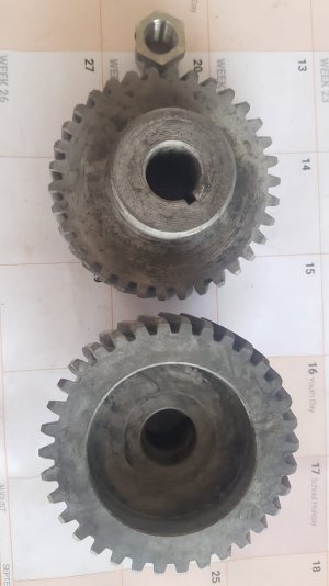
I dont have the gears in hand yet so I can't give diamentions except for tooth count which looks like 34T. The customer sent the pics for me to have a look at.
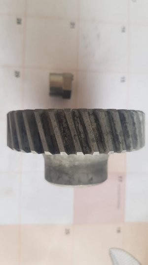
IMG-20230214-WA0025.jpgIMG-20230214-WA0024.jpg

Any advice is welcome,because like I said it will be my first hellical gears. I will be doing some homework in the meantime,but there is thing like too much information.

Thanks for viewing.
Michael.
 
Few notes:

Unless you know the helix angle of an existing gear, it's really hard to determine the exact helix angle... Chiefly because you have to measure it at the pitch diameter which is also not trivial to determine. Helicals are often profile shifted, either to increase strength of the teeth or to make for a more convenient meshing distance.

Realising that the helix angle changes as you move up or down the profile of a helical tooth is key to understanding that "one does not simply measure a helical". Not that I want to put you off, just setting the expectation!

This module or DP? What's the application?
 
When I have cut helical gears, I just take a protractor, for a combination square and measure the angle by eye, make a calculation and determine the lead of the spiral and set up the dividing head with change gears according to the table of leads in Brown & Sharp's book on milling, and mount the old gear on a mandrel between centers with a driving dog, and rotate it and indicate a tooth with a test indicator to prove that the lead is correct, if the lead is too long or too short, I set up another set of gears accordingly, it generally takes only several setups to find the correct lead.
Note that it sometimes takes a different cutter to match the tooth profile of a helical gear than the number of teeth that similar spur gear would have.
 
I would estimate the pressure angle and helix angle and use a 3D printer for making a prototype. Once that 3D printed gear is OK, I would make one out of steel or POM.
Beware that cutting a helix gear using an angled dividing head on a manual mill, isn't a real helix gear but could work for larger gears.
This is how I make my (helix) gears:
 
set up the dividing head with change gears according to the table of leads in Brown & Sharp's book on milling,
I don't have a book like that,but I did get some formulas from the machinerys handbook 20th ed. but I dont see calculations for the gear ratio of the DH yet. I do know my DH has a gear ratio of 40:1 and when I turn the mill lead 40 times,the bed moved 116mm. I also know the OD of the gear is 79mm , 34 teeth,gear lengt is 20mm and lead angle about 15°. I do not know how to get to the gear ratio and gear sizes to use on the Deviding Head.
 
My video might help you:


I'll find the spreadsheet for you too, it's so much easier than manual calculation. I'm sure someone will be along to tell me long division is the only proper way to do it, mind :laughing:
 
My video might help you:


I'll find the spreadsheet for you too, it's so much easier than manual calculation. I'm sure someone will be along to tell me long division is the only proper way to do it, mind :laughing:
I'll appreciate that spreadsheet. I will do the long devision too....I like to learn so if I can do the math then the spreadsheet will be a bonus and I will understand it better. Thank you.
 
Back
Top