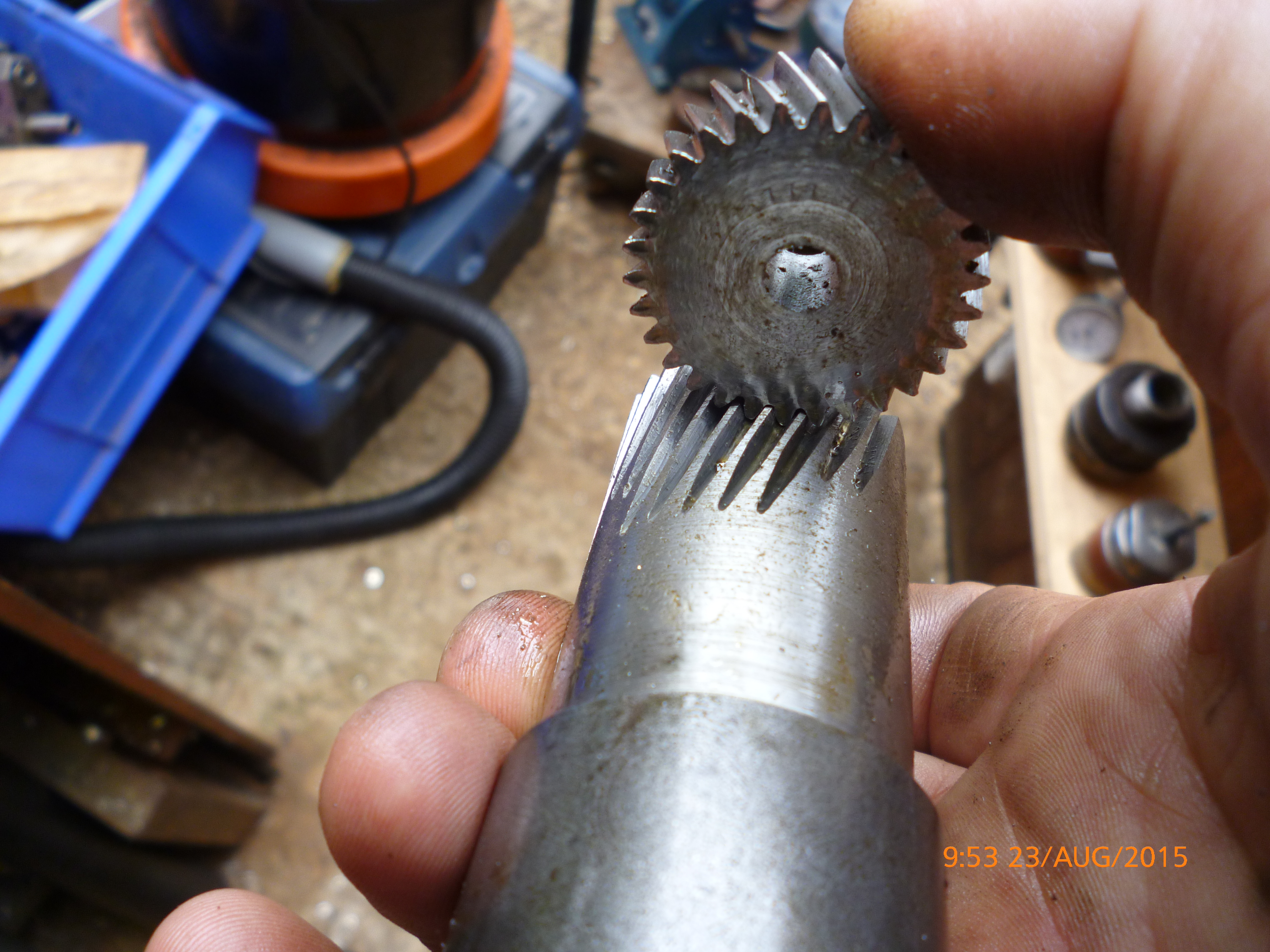
Helical gear calculations

I'll appreciate that spreadsheet. I will do the long devision too....I like to learn so if I can do the math then the spreadsheet will be a bonus and I will understand it better. Thank you.

Hopefully it's self explanatory! If not, ping me and I'll go through it here so anyone else stumbling across the thread in the future gets the benefit :)

I've attached a handy dividing head calc sheet too, though that's better served by the software I wrote that handles differential too.

Licensed Creative Commons CC-BY-SA
 

Attachments

  • Helical calc.xlsx
    14.4 KB · Views: 9
  • BS0_DividingHead_Calculator.xls
    206 KB · Views: 4
In my method, the spiral angle is measured from the centerline of the old gear, say, it measures 57 degrees, the formula to calculate the lead in inches per revolution is: Lead= the circumference of the part (where the angle was measured), divided by the tangent of the angle as measured. The lead is then looked up in a handbook such as the Brown & Sharpe milling book or Machinery's Handbook in a table of leads and the appropriate change gears are selected and mounted on the machine and dividing head. Most all dividing heads are in the 40:1 ratio, ditto the tables.
As an example, one job I did was a gear that was 3.863 in diameter and measured as approximately a 57 degree spiral with the centerline. The 3.863 diameter X Pi = 12.136 divided by the tangent of 57 degrees (1.5398) = 7.881 lead. Looking in the table of leads, the nearest lead is 7.883 and gears listed are: gear on worm (dividing head) 86 tooth, first gear on stud 48 T, second gear on stud 44T, table screw gear 100t.
Spiral gear cutter selection; From machinery's handbook, 2nd edition pg216, c 1914.
Divide the actual number of teeth by the cube of the cosine of the tooth angle; the quotient will equal the number of teeth to select the cutter number. As the angle increases the cutter number is smaller. This for USA cutters, for foreign made cutters., the cutter number could be larger.
 
Last edited:
As earlier stated, I set up the old gear on centers on the dividing head and then indicated to tooth in an undamaged tooth and if there was a discrepancy in the reading, I looked back in the tables and set up another set of change gears until the indicator registered little or no movement when indicating on a tooth and traversing the table over the length of the tooth, it usually only took a few gear changes to accomplish.

To check the lead by setting up existing gear to indicate a tooth:

RH spiral
If in indicating an existing tooth to prove the lead is correct, in a trial setup, if the indicator is set at zero at the footstock end of the gear, and in moving towards the headstock end there is a negative reading or a space between the indicator stylus, shorten the spiral lead.
If a left hand spiral, and the indicator reads plus at the head end shorten the spiral lead.

Indicating is done on top of the tooth, generally on the front of the gear, facing the operator and can be done on any part of the face of the tooth, not just at the pitch line, but also can be near the OD or root.
 
Hopefully it's self explanatory! If not, ping me and I'll go through it here so anyone else stumbling across the thread in the future gets the benefit :)

I've attached a handy dividing head calc sheet too, though that's better served by the software I wrote that handles differential too.

Licensed Creative Commons CC-BY-SA
Please bear with me. I get some of the numbers but not all,soooooo if you can go through it??? Sorry if I am a bit slow.
 
In my method, the spiral angle is measured from the centerline of the old gear, say, it measures 57 degrees, the formula to calculate the lead in inches per revolution is: Lead= the circumference of the part (where the angle was measured), divided by the tangent of the angle as measured. The lead is then looked up in a handbook such as the Brown & Sharpe milling book or Machinery's Handbook in a table of leads and the appropriate change gears are selected and mounted on the machine and dividing head. Most all dividing heads are in the 40:1 ratio, ditto the tables.
As an example, one job I did was a gear that was 3.863 in diameter and measured as approximately a 57 degree spiral with the centerline. The 3.863 diameter X Pi = 12.136 divided by the tangent of 57 degrees (1.5398) = 7.881 lead. Looking in the table of leads, the nearest lead is 7.883 and gears listed are: gear on worm (dividing head) 86 tooth, first gear on stud 48 T, second gear on stud 44T, table screw gear 100t.
Spiral gear cutter selection; From machinery's handbook, 2nd edition pg216, c 1914.
Divide the actual number of teeth by the cube of the cosine of the tooth angle; the quotient will equal the number of teeth to select the cutter number. As the angle increases the cutter number is smaller. This for USA cutters, for foreign made cutters., the cutter number could be larger.
Thanks Ben. Sadly I only had the gear a few minutes to take measurements, because the client had to send it away to his client. A bit annoying, but what can I do. How do I determine the lead angle of my mill again? I am blanking out a bit. I must try to keep up with converting everything to metric before or after doing the math. I wanted to double check the helix angle of the gear before they took it, but forgot (rushed). I think I measured from the wrong side and got 15° but I should have measured from the horizontal to the vertical and then the helix angle should be 75° right? I am trying to get a drawing out of the end clients for the gears and preferred material for it. My client is looking for a new supplier of the gears (hopefully me) to supply his kliënt.

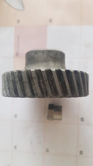
Don't know if you can roughly determine the helix angle from this pic. Does 75° looks like it can be in the ballpark? Or was I right the first time because I just read that common helix angles on helical gears range from 12° - 20°
IMG-20230214-WA0025.jpg
 
Last edited:
you measured 15 degrees from the side of the gear, the complement would indeed be 75 degrees from the axis of the gear, for purposes of computing the lead in inches, which should be simple if you compute the circumference and divide by the tangent of that angle; that should give a close approximation of the lead that can be proved by setting up the old gear as I directed. When you perfect the actual lead, I have another approach to calculate the setting of the swivel table on the milling machine. I will post it separately.
 
Table angular setting for spiral cutting:

Re figuring the spiral angle of the corrected lead:
Tangent of the spiral angle = circumference divided by the lead.
example: Tangent of the spiral angle = 3.3206 (circumference of the 1.057 diameter) divided by the 4.186 lead, equals ,79326
From the table of tangents that equals a angle of tangents, .79326 equals and angle of 38 degrees and 25 minutes, or nearly 38 1/2 degrees, set the table swivel to that angle, after centering the cutter centerline to the dividing head centerline.

Don't worry about this info needing to sink in right away: I did quite a lot of head scratching and reading to write all this for my own use, my grades in math were not very good, but I struggled along and was able to get what I needed for shop work; once I saw the application of math in my world, it became easier to deal with. If I was good in math, I would have gone to engineering school, lacking grades and understanding I went into apprenticeship in a machine shop, I have never regretted it.
One detail, if one wishes to compute gear ratios for such as spiral gears, Brown not do it by multiplication/division, they had a method akin to long division known as "continued fractions" The process is detailed in their milling book, which I'm told is available online or from E Bay in book form from time to time, also perhaps from online book sellers as a used copy.
Me and you are on the precise exact page. When I read this part,I thought I wrote it.

I think I must mention the tools available.

Knee vertical mill (No swivel bed,head can tilt side to side)

BS-2 universal dividing head(may short some gears,mounting brackets and gear arbor)
Screenshot_20230214-213700.jpg
I have this model,shorting the bottom 4 items in the pic and only have the following gear sizes and don't know which are missing. Z40, Z48, Z56, Z64, Z72, Z88 and Z100. I have contacted HOMGE MACHINERY for a quote , but no reply yet. I can make the parts,but it will take a lot of time.
 
I was under the impression you needed a universal type milling machine with a swiveling table to cut these types of gears.
Is this not true?
 
I was under the impression you needed a universal type milling machine with a swiveling table to cut these types of gears.
Is this not true?
I will say not true. I found this very helpfull link. Check it out.

 
Back
Top