[How do I?] Help Me Build My Bogies

Spindle speed in RPM = Cutting speed for material X 4 / work diameter. The cutting speed for aluminum varies but is in the range of 150-400 SFM. Say we choose an average of 250 SFM. 250 SFM X 4 / 1.5" (the diameter of your workpiece) = 666 RPM spindle speed. I suggest you try the B-F setting and see how it works.
 
Thanks Mike, this forum is great. It makes it so much easier than having to research all this stuff. At least I have a good idea of what questions to ask. I'm going to start a notebook to keep in the lathe bench with all these formulas and tool bit angles, etc. I just ordered the 1/8" stainless axle rods today. I got it from a guy on eBay named highdesertmartin. I'm going to need those to experiment with till I get my center hole diameter just right.
 
James, I don't know if you have given much thought to the profile that you intend to use on your wheels, as you did not make any mention of it in the thread thus far except that you intend to place an angle on the wheel flange. I don't mean to poke my nose in where it need not be, but speaking up now may save you many headaches from frequent derailments and constant frustration. I will include the details here for the benefit of everyone that reads this.

Railroad wheels and railheads have their own special shapes for many reasons that are not always obvious. Wheel treads are not parallel with the axle center line, but instead are angled almost 3°. Railheads are slightly rounded in full size practice, but flat topped rails work with satisfactory results in the smaller sizes such as most of the common model gauges and even up to 7 1//2" gauge, though some objectionable wear patterns may appear on the wheels of the larger gauges when using bar stock to create flat topped rails. Wheel profiles become even more important when flat topped rails are used so that derailments can be avoided. To begin with, here is a link to the IBLS (International Brotherhood of Live Steamers) wheel standards. The drawings on that page do a good job of showing the correct wheel profile that you will want. The IBLS does not directly address G gauge, as those standards originated in Germany and are much more prevalent in Europe. Those standards are available here: G Gauge Wheel Standards.

Some may ask why a flat wheel tread will not work properly, and I will address that here very soon, along with the purpose of the other angles on the wheels. I do need to leave for a family function, but I will address this further when I return, later today.
 
Last edited by a moderator:
Thanks, Terry------ I was just about to discuss the same thing, but a book can
be had with the necessary dimensions and profiles for model railroads, and
little or no extra cost or effort is needed ; will work much better .........BLJHB.
 
Thank you very much Terry for bringing this to my attention. I actually have a G-scale bogie here that I am modeling after. I took it off one of my Bachman trains. This Bachman bogie is entirely injection molded plastic. But the one I am planning on making is very close to this in design. The main difference is that my bogies will have the chassis parts made mostly of brass. And the wheel will of course be aluminum as I have planned (at least for this first batch of bogies). I can always change materials down the road as I get better at making these.

But yes I see the angle you are talking about on the surface of the wheel that rides on the rails. These Bachman bodies have that angled surface. Thus far my drawings (and everything I've done up to this point is just prelimiary drafting work). I'm only just now learning to use Sketchup, so much of the learning curve is just on how to draw things up in 3-D modeling.

Before I actually make the wheels I plan on measuring these Bachman wheels precisely and try to duplicate them as best as possible. But you're right my original thinking was that these wheel would just be flat on the surface that rides on the track. But they aren't. So thank you for bringing this to my attention. That's what I cam here for, HELP!

So don't be afraid to point out anything I'm doing wrong. Obviously I may be determined on some things like using cheap materials (hee hee), but overall I'm totally open to any observations or input that will help to make these bogies the best they can be, even if I do cheap-out on materials. :grin:

Like I say, if I get good at making these and things are going really well, I might be encouraged to make some really nice ones out of more costly materials.

But yeah, if you have information that will make these bogies more dependable all the better!

As far as my track is concerned, the rails are going to be wooden which will no doubt bring up many issues on its own. I am hoping to get by with a totally flat-top rail (or at least a flat angled top). But it is possible that I could take care to do some work on the rail profiles too. I'm also anticipating a "slippery" problem. I know that wet wood can be extremely slippery. Especially if it's been oil-stained. And I'm considering potential "fixes" for that already. The two possible solutions I have thought of up to this point is to either make the wheels of the locomotive rough so they grab the wood (and potentially sand down the rails over time). Or I could "dust" the rail tops with a fine grit after having wet them with glue and let the rails "sand down" the aluminum wheels over time.

I haven't decided exactly how I might deal with any "slippery" problems. Although that really should only occur when the rails are wet. I don't think there should be a slippery problem when the rails are dry. Only time will tell on that one. One of the first things I'll be doing is to build a long straight stretch of track, and then see how steep of a climb the engine can make before slipping. I can also wet the track down and see how that effects things too.

This whole project is a "Work in Progress" and it could potentially fall flat on it's face and not be doable. But I have faith that I can overcome these potential problems.

But yes, you're right, getting wheel and rail geometry right to begin with will be a huge plus as I move forward to tackle these other potential problems. So all suggestions and observations are welcome to be sure.

That's what I came here for, HELP! Yep, no point in trying to do this alone I can't think of everything.

Thanks for the link to the IBLS Wheel Standard page. I'll definitely be studying that in depth.
 
RAILS AND WHEELS - PART II

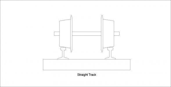
Okay, first we'll talk about the wheels, as they have the greatest effect on what happens with the behavior of a rail axle, truck, and car. As mentioned earlier, the wheel tread is angled nearly 3°, (a maximum of 2° 50') for IBLS standards, but the standards for G gauge call for a straight 3°. I have included a drawing here with the tread angles slightly exaggerated so that the physics are more apparent. This drawing is of a set of wheels on straight track. Click on the thumbnail to see the full sized image.
Rails and Wheels001.JPG

When the truck is traveling down straight track, it is easy to see that gravity will tend to center the axle on the rails, and the flanges are totally unnecessary to stay on the track. In reality, if the car were loaded heavy on one side, the wheels would tend to move over a little bit to self center the load, correct? NOPE. Here is why: We all know how cars and trucks have differential gears on the drive axle so that turns or curves can be negotiated while allowing the two drive wheels to turn at different speeds yet allow for the longer distance that the outside wheel has to travel. Right? Okay, so what happens with a rail car axle? It is solid, no differential gears, both wheels are solidly affixed to the axle, requiring that they both turn at the same speed as they negotiate a curve. This creates a bit of a quandary, doesn't it? It maybe even goes against everything that we've learned before. Well, the axle will center itself between the rails (regardless of uneven loading) until both wheels have the same diameter in contact with the rails, allowing them to travel at the same speed as they head down the track. In a perfect world we wouldn't even need the flanges at all. Have you ever been watching a train as it goes around a curve or through a switch and you hear loud screeching from time to time? That noise is what is known as 'flange squeal' and it is caused by the flange coming in contact with the side of the rail. As the flange rubs the rail, it does so with a wiping action, causing the squeal. That wiping action is also what can cause a wheel to climb a rail and cause a derailment if the wiping action is strong enough. It seldom happens on straight track, but becomes more prevalent on curves or when going through switches when the flanges are said to 'pick' at the rails.

So we are headed down straight track, the cars are running centered on the rails, and there is little if any flange squeal. Perfect! There is also very little rolling resistance due to the very narrow contact area between the wheel and the rail, but the rolling resistance increases significantly when a flange starts rubbing on a rail, such as on a sharp curve. Full sized railroads actually install 'flange oilers' just prior to track with severe curvature. The oil on the flange reduces the friction between the flange and the rail, reducing the power required to get the train around that curve but even more important, it helps reduce the wiping action that could potentially cause a wheel to climb the rail and derail.

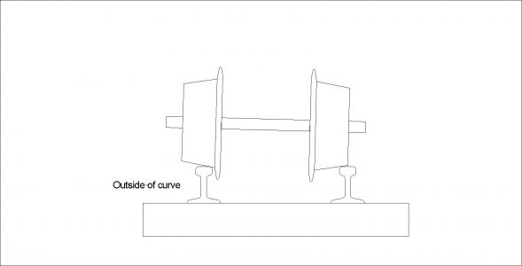
Since we are talking about curves, how do the axles on rail cars deal with the longer rail on the outside of a curve? There is no differential, so just how does this work? Quite simple! Refer to the drawing below.
Rails and Wheels002.JPG

We already know that the wheels will find their own happy medium on straight track, and for the most part they do the same thing on curved track as shown in the drawing. Both wheels are turning at the same speed, but the axle will shift toward the outside rail so that the effective larger diameter of the outside wheel will turn at the same speed as the effectively smaller wheel on the inside rail. This also gives the added advantage of slightly elevating the side of the car that is nearer to the outside of the curve, helping to move the center of gravity toward the inside of the curve, which in turn helps to counteract the centrifugal force created by traveling around the curve. WOW! It's like magic! Well, not really, but I will bet that most folks never realize just how much science is taking place on a simple railroad track.

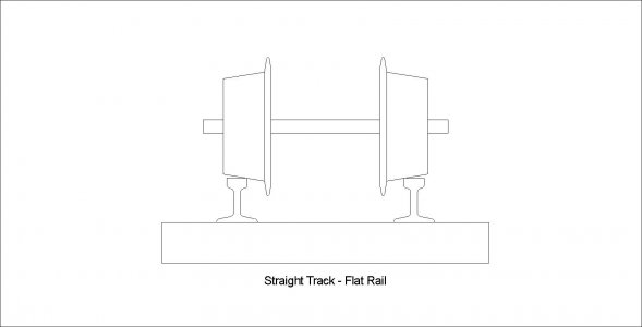
So okay, now we know why the wheels have an angled tread, so let's have a look at the rail. Granted this is not too important in the small gauges, but it is good to be aware of just the same. First we will look at flat topped rail as shown in the image below.
Rails and Wheels003.JPG

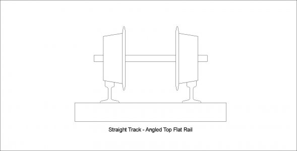
As we can see, the contact point between the wheel and the rail is very, very small. The problem with this is that the load placed on that point of the rail will tend to cause the corner of the rail to fracture and crack. We all know what happens with cracks: once they start, they keep on going, right on through the entire rail. Using rail that has a slight radius on the top allows for a small contact point for reduced rolling resistance, but the wheel contacts the rail on a surface that is well supported and less prone to load fracture. Okay, so that was easy, why not taper the top of the rail to match the wheel tread?
Rails and Wheels004.JPG

Very simple, and it should be obvious based on the drawing above. Here we effectively have an unlimited number of diameters contacting the rail, all turning at the same speed. Only one diameter can run true on the rail, which one will it be?? Don't know, most likely the largest diameter I suspect as it would have greater leverage over the smaller diameters. But, the rest of the wheel tread would be scrubbing on the rail the entire time. The rolling resistance would be PHENOMONAL! Not a good thing.

So how does all of this affect our model trains? As we can see the tapered wheel treads will still be a necessity, as well as the angles on the flanges and the radius on the very outside of the flange diameter. The angles and radii on the flanges help to reduce rail picking and flange scrub, reducing it to one small point rather than occurring across the entire flange. This all reduces rolling resistance, allowing a smaller locomotive to pull a much longer and heavier train, while greatly reducing the chance of a derailment. As for the rail material and shape, the wheel loading is not nearly so high with our models as with full sized railroads, thus flat topped rail will work without causing rail failure. Remember that in theory the contact point is infinitely small, regardless of the size of the wheel, yet the loading is far greater on prototype equipment. This is why full size tracks are made of high grade steel while many live steam railroads use aluminum rail and it works just fine because the load at the wheel/rail contact point is just a tiny fraction of a full sized wheel. As the models get smaller, this loading is reduced even further, yet the actual contact point remains the same size for all practical purposes.

So, in my estimation, there comes a point where wood rails should be feasible, and G gauge might just be the size to try it on. A flat topped rail should work, as the corner of the rail would simply compress slightly over time and might even give a slightly curved surface over time. Personally I suspect that you will see little change in the wood over time. I would not be to concerned about it being too slippery when wet as I suspect wood will have a better overall coefficient of friction compared to steel or aluminum, wet or dry.

James, the only thing that I would consider differently for your project would be the material for the wheels on the cars. These cars are very light and are lightly loaded, thus there is no real need for metallic wheels. I would try black Delrin first, and if it did not meet my expectations, then I would try aluminum. Delrin machines very easily, and it is already the right color for wheels. You could rough machine your wheel profiles then use a couple of form tools to get the final wheel profile that you are after. They would also press onto the axles very nicely and you would not have to worry about corrosion between dissimilar metals that would occur between stainless steel and aluminum. Delrin is also self lubricating for the most part, you could make your axle journals out of Delrin also.

One other thing, James. You don't need to measure the Bachman wheels. Click here for G Gauge Wheel Standards

So there you have it gentlemen, a quick explanation of why rails and wheels are shaped as they are. There are other details that I did not go into, but they are small things that do not really cause any issues in model gauges.
 
Last edited by a moderator:
Thank you very much Terry for the detailed presentation. This was knowledge that will definitely come in useful for me. I confess that I've been thinking along the lines of "It's just a model", so I was thinking that thing don't need to be too critical, but that's no doubt very bad thinking on my part. I'll take all of this into consideration.

Also, one of the things I've been thinking about is that the standard G-scale rolling stock is quite light. Especially these plastic Bachman trains I have. My entire railroad will be elevated about 2 feet from the ground, sometimes as much as 4 feet due to uneven ground. The railroad itself will be pretty level. But my first thought is that if a strong breeze comes along these lightweight trains could potentially get blown off the track and fall to the ground becoming severely damaged. I'm sure that's inevitable in the long haul, but I don't want it to become an everyday event. Eventually I'll be replacing these Bachman trains with my own scratch built rolling stock mounted on these homemade bogies I'm currently designing. I'm planning on making my rolling stock a bit heavier overall. Not by much, but definitely heavier.

The other thing too is that I will be converting these trains over to battery power. My thinking is to distribute the batteries throughout the train rolling stock. This will also weigh the cars down a bit. I'm thinking of using use AA rechargeable batters in banks mounted under the carriages of the rolling stock. this will keep the battery weight at a low center of gravity and will also free up flat cars and gondolas to be able to actually carry payloads instead of batteries topside.

The trains I plan on running won't be very long though, maybe only 5 or 6 cars long plus a caboose. If I go as many as 7 or 8 cars that would be a really long train on my tiny layout. I'll have to post a drawing of the actual layout.

So while my cars aren't likely to be as heavy (in proportion) as an actual train, I do plan on having some weight to these cars, both for holding batteries and for more stability should a gust of wind come along. I also plan on having "live" operations in terms of loading and unloading the cars. For example, I hope to be modeling a sawmill, so I have logs loaded onto the cars via automated cranes, and then I might have them "dumped" off when delivered. Then there will be stacks of lumber loaded onto the train and unloaded at delivery points too. So the railroad model will be "operational" in that sense. I'm not really thinking about uncoupling operations so much. Since my trains will be powered by batteries under every car they will all need to be wired together. So uncoupling cars would also require unpluging the electrical connections, etc.

In any case, I was out working in my shop today, just cleaning things up in preparation to start in on this railroad building project. Just cleaning up the shop played me out and I had to come in an lay down to recover. So this whole project might be more than I can realistically deal with. I'm trying to recover a childhood dream whilst living in the body of an ailing old man. Not sure if this is going to actually work. I was hoping to get a lot more done today in the shop than I was able to actually do. :apologize:
 
It looks to me like you have thought much of this through already. Using the batteries as stabilizing weight is a good idea. Adding batteries to the loco if possible is a great idea also, as the added weight helps with increased rail adhesion by the drive wheels.

Good luck with your project. It may seem a bit ambitious at times, but Rome wasn't built in a day. You can accomplish your goals by taking small steps, making one piece at a time. Hang in there!
 
James,

Thanks so much for your response. Very interesting. I actually think your wooden rails will be fine, if treated properly. As you know, aging of the wood will be critical.

Just curious, but have you considered epoxy impregnating your rails? You could even add some grit to the top of the rails (fine glass filler or other fillers like this stuff) to help with sliding.

I made some aquaria from epoxy impregnated plywood about 15 years ago, and they are still being used. I used a reduced epoxy that I soaked the boards in, and then applied epoxy + hardener to these soaked boards. I figured the hardener (which is a catalyst) would continue to permeate the un-catalyzed resin in the boards.

Cheers,

Tom
 
Tom,

This whole project is definitely a novel idea and I expect to have some unforeseen potential problems as things progress. I don't know whether I'll have a problem with slippery rails or not. I was just guessing that this could be a potential problem so I'm considering potential solutions should this be a problem. It will certainly be wroth investigating early on in the project. When I build my first wooden track I'll experiment with it by seeing how steep of a grade the locomotive will be able to negotiate without slipping. Then I can wet the tracks down and see if that makes a big difference in traction. Although I'm not too concerned with running the trains on rainy days anyway. But it would still be nice to figure out what all the limitations are early on. My railroad overall will be pretty level. I do plan on having some small grades in places, but those particular places are "ambitious dreams" which won't be realized for quite some time. The first part of this project is going to be pretty much perfectly level track.

But yeah, when I start to actually build some track I'll do some extreme experiments to see what the limitations are. If the track proves to be extremely slippery then I'll be forced to start thinking of solutions to that problem. At this particular point in time I really have no clue what to expect. I'll have to wait until I build some of my first track and see how well it actually works "as is" before I tackle problems that don't yet exist. But yeah, using some sort of adhesive to add some "grit" to the rails is one possible option. The other option is to add the "grit" to just the locomotive wheels which actually sounds more practical. But I'll have to wait and see what the actual problems are, if any.

~~~~

Terry,

I found your presentation on the geometry of bogie wheels extremely useful. I've been studying up on this to see what might work best for my specific situation. I haven't done any actual calculations yet, but I did push this Bachman Bogie around a curved section of track to see how the wheels actually work and I immediately noticed precisely what you said. When rounding a curve the outside wheel runs on its inside diameter (the larger diameter), whilst the inside wheel runs on it's outside diameter (the smaller diameter). This got me to thinking that the best angle for my specific layout might be to set those wheel diameters (or angle of the flat) specifically for 24" radius curved track, since that will be the radius I'll be using. I'm not sure if that's what Bachman set there's for or not. But I imagine that real railroads don't have nearly as sharp of curves. So using prototypical wheel dimensions might not be as good as recalculating this specifically for my 24" radius curves. That might end up giving me a steeper angle on the flat of the wheel than is recommended in terms of normal railroad prototypes.

I'll definitely look into this. I haven't done any actual calculations yet. But as soon as I find time I'll do those calculations and then draw up the results. I can draw up what they recommend verses what I end up calculating for 24" radius curves. Even my turnouts will all be 24" radius curves because I'll be making those myself and I've already designed a router table to cut these 24" radius rail grooves.

I'm really glad I started this thread on this forum. I've already learned quite a bit here. This sure beats trying to do this all by myself! I can't possible think of everything. This wheel geometry is extremely important and I was totally unaware of the dynamics behind this until you came along and explained exactly why all these angles are used and what the physics is behind them. Now I have a much better understanding of what I'm setting out to build. Previously I though, "Eh,... it's just wheels", but now I see there's a lot more to it than that. So thank you very much for enlightening me on the physics of railroad bogie wheels.
 
Back
Top