Help with gear

I cut a vee one half way through from the top so the backside would mate perfectly, then made a special clamping arrangement that held it all in place. I preheated with oxy acetylene, then got it cherry red, used a rod made for cast iron, dipped it into flux and the rod either pooled or ran off. I could not find a happy medium where it would stick and puddle. I got some to stick but it did not fill the vee. I am clearly just not experienced enough to pull the brazing off. Also I suspect I could use better rod/flux. I also do not have a tig setup, only mig, so I didn't even try tacking it with the welder.
That's not brazing! Using a rod made for cast iron is welding. This works completely differently from brazing. It also requires some degree of skill. The base metal has to be melted pretty completely. It gets pasty under the flux, so it doesn't really drop through. The weld region is pretty large, and I would never attempt this on a gear. It requires a lot of heat.

Brazing is getting the metal bright red, but nowhere near melting, and melting brass over it. At the right temperature, the brass is quite fluid and moves around pretty well compared to the cast iron welding rods. The cast iron rods are kind of sluggish, and they end up leaving a pretty blobby deposit, which can be left or machined off.
 
It wasn't a cast iron brazing rod, but a brass brazing rod made for brazing cast iron.
 
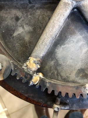
Both responses simplify matters a great deal. As a functional gear, appearance doesn't matter, and being in the carriage drive train can be brass, aluminium, or even plastic. As for the original, busted like that it likely won't be recoverable. A real old time machinist might be able to repair the gear, when he was so drunk he couldn't walk. Maybe. . . But an amateur wouldn't be able to restore a usable gear. Stick the pieces together, sure. Even I could do that. But to line up everything where the teeth would be usable, not very likely.

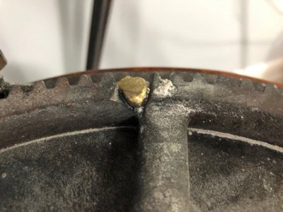
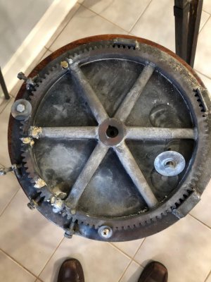
You will want to reassemble the gear enough to determine the details. Nothing accurately, just enough to get bore diameter, overall diameter, tooth count and pitch, thickness at the bore and at the rim. Being a change gear, likely is consistant thickness. But be sure. Once the details are noted, keep the pieces to chunk at a 'possum or a 'coon. Bore diameter and pitch can be determined from another intact gear in the train. The bottom line here is that once these are known, there are innumerable ways to deal with a replacement.

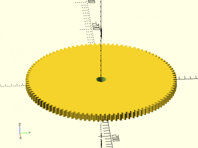
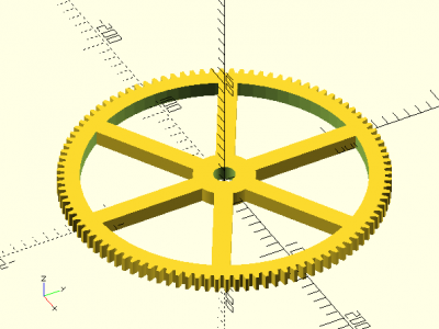
Simplist is to go to a vendor, such as Boston Gear, to get another gear. They might not have the thickness you need, change gears are usually thin and "flat". Running gears will have a wider rim (teeth) and hub and need to be faced down. If you have access to a 3D printer, make one. Or get a friend to. A gear can be cut on a lathe. It takes a little tinkering to get all the misc pieces together, but doesn't require the lead screw to run. A gear cutter is the most optimal but can be done with a lathe tool ground to the proper profile. You have the broken gear as a pattern, just grind a tool to match.

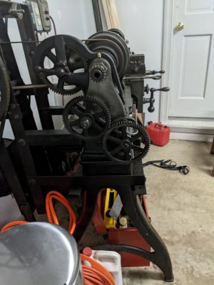
Change gears can be thought of as "timing gears", there is little torque involved. Just enough to turn the lead screw. Aluminium makes a good choice here, my Atlas built machine uses ZAMAK, a zinc and aluminium alloy, for change gears. I also have an Asian machine that has cast iron(?) gears. There are many users here that have 3D printed change gears. The plastic holds up quite well in such a low torque use.

Gear pitch will be dependent on the lathe. My Craftsman/Atlas has 16DP gears. The Asian machine uses Modulus 1 (25.4 DP). When and where your machine was built will determine the pitch. American machines use both systems, DP being the most common. Asian and European also use both with Modulus being the most common. A lathe is often refered to as the "queen" of machine tools. With the appropriate knowledge, it can build itself. Repairing itself is a derivitive of that. Everything (literally all) you would need to know is in "Machinery's Handbook". A recent copy is a little overbearing with all the leading edge technology they have. The ones from around WW2 to about 1960 are the most useful to the amateur. Less sorting out of hi-tech stuff to go through. The end result is that you are looking at time and knowledge being the only limiting factors. The actual gear is a piece of cake.

.
Thanks for the book reference, I will get a copy, and thanks for the other advice as well, I really appreciate your time in responding. The gear is a 10DP, 14.5 degree, 104 tooth gear with a .719" bore hole, .6" thick, but in its use, the thickness is not critical. I created a cad model, rewrote the involute gear code in the cad tool because it was all wrong, and laser cut a MDF gear to test fit. The MDF gear meshed well and worked when I spun everything by hand, so I have the gear parameters down pat, and I have a cad model if that is useful.

I can't figure out how to cut the gear on my lathe since the size is so large, 10.6" diameter. I can't hang a rotary table off the side far enough, and cant figure out how to raise/lower the rotary table so the the tooth cut is not deeper in the center than the outer surfaces. I would be fine cutting one of the smaller gears, but this one large gear is more of a problem. I think I just don't know enough about how to do this, and also don't have the right equipment.

I did ask Boston for a quote on the gear, it would require a second mortgage in order to get them to look at it, and would be 4 magnitudes more accuracy than the original.
 
Ya'll asked for pictures, The last 2 are cad models of aluminum (no spokes) or steel (with spokes).
 

Attachments

  • joint.jpg
    joint.jpg
    103.9 KB · Views: 11
  • otherjoint.jpg
    otherjoint.jpg
    115.3 KB · Views: 10
  • unnamed.jpg
    unnamed.jpg
    81.4 KB · Views: 10
  • mygear_aluminum.png
    mygear_aluminum.png
    10.8 KB · Views: 8
  • mygear_steel.png
    mygear_steel.png
    18.5 KB · Views: 7
I have a 10” gear but not sure of number of teeth. Might could find a manual flywheel starter ring gear of correct size
 
I have looked, but getting the combination of pressure angle, teeth, and DP has turned up no options. There is a 104 tooth gear about the right size used on a 70s Jaguar flywheel, but I can't verify the pressure angle or DP. That is as close as I have found.
 
Sounds like you need another machine tool;)

John
 
Oh wow, those are informative pictures. That must be pretty tough cast iron. I would have expected to see a lot more flux. The brazing flux is really tenacious when it flows in and requires a lot of chipping or grinding to get it off. It won't fall off by itself or get removed with a wire brush. It almost looks like not enough heat and flux. Experts use just enough flux. I use an excess and it gets all over the place. Usually, I'll just play the torch over the metal and warm it up. Then, touch a rod dipped in flux occasionally to the heated spot. Don't melt the rod. Eventually, the flux will start flowing and more can be added. It helps conduct heat around too, so the joint stays at a more even temperature. Good flux should wet in at a decent red heat. Brass won't melt until bright orange. The cast iron is not in danger until yellow.
 
I had the gear cherry red. It would not melt the rod unless it was real hot. I might try this again with new flux/rod. Any recommendations for specific products??
 
Everyone on this thread has been so helpful. I had an idea, and wanted to get an opinion if it sounds good. All the change gear ratios either use this gear paired and locked to a 52 tooth gear, or use just the 104 tooth gear. The ratios in the gear chart below that have a black for the "stud" gear use the 104 tooth gear only, and it engages both the spindle and screw gear. Thus the 104 tooth gear is used to either have a gear ratio of 1 when alone or 1/2 when paired with the 52 tooth gear. I am thinking that replacing both gears with a 100/50 tooth pair would preserve the ratios. 100 and 50 tooth gears are catalog items, whereas the 104 tooth is not. Does this sound reasonable???

The pictures below show the gear ratio chart and a typical usage with my mock up wooden gear. The spindle on top, the stud gear as shown is in divide by 2 configuration with the 104(wooden) gear and the 52 behind it. woodruff keys on the bushing lock the 104 to the 52. On the bottom right, I think is a 48 tooth on the screw, for a 24 TPI ratio.

View attachment 391373geartrainend.jpg
 

Attachments

  • endview.jpg
    endview.jpg
    67.6 KB · Views: 5
Back
Top