How Would You Make This Part.

"I don't quite have enough Y travel on the CNC mill to make that work."

What if you mounted your 4th axis vertically and mounted the handle on it, you could rotate the table and not have a y axis travel issue.


98312-2301838e12620ff818546c8e9a207ce5.jpg

Kevin

Hand wheel.PNG
 
banned for 1.5 months for suggesting someone buy it, particularly when they ask for assistance with how to make it.

Awww...c'mon, I'm not that bad. Ok, I will back it off a bit.
 
If it was me I'd be looking at dumbbell weights. Not aluminum but cast iron is more industrial. :)
This particular 2.5 lb. one is 4- 3/4'' in diameter, cuts really well on a lathe.
Maybe a 5 lb weight would be large enough for your project.

IMG_0063.JPG

IMG_0064.JPG
 
Another good idea for collet closer hand wheels is to put some radial holes in from the O.D. so a round bar can be used as an extension lever if it gets stuck or if you think you need something a bit tighter. Also good if your hands are getting arthritic, like mine are... :(
 
Another good idea for collet closer hand wheels is to put some radial holes in from the O.D. so a round bar can be used as an extension lever if it gets stuck
hmmmmmm.......or even for some makeshift indexing........
-brino
 
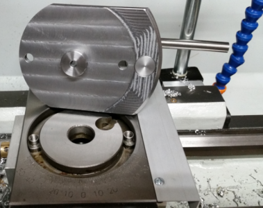
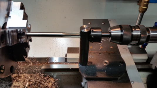
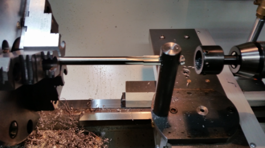
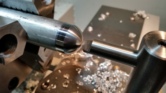
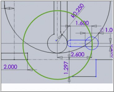
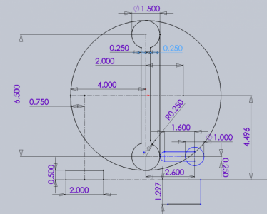
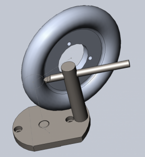
After mulling over the various ideas I came to the conclusion the radius turning tool was the way to go. Getting the radius cut on the inside the pocket of the web presents a bit of a challenge. I worked out the geometry in CAD and came up with a design that was simple and could cut both the large and small radius's.

RTCAD01.png RTCAD02.png

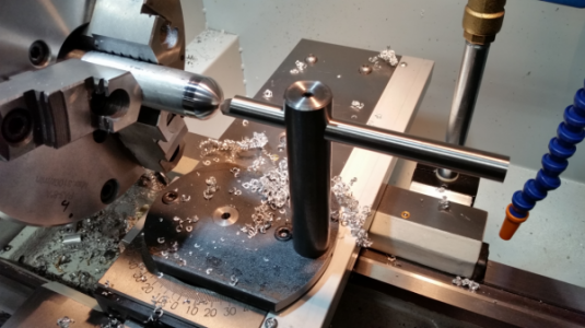
The base is 1/2" x 4" steel. The tool holder is 1" steel rod. The tool is a 1/2" x 6" round HSS tool blank profiled to 1/4" radius cutter. It also acts as a handle. For use the radius tool replaces the compound. The tool holder and pivot boss are pressed into the base plate. The pivot boss has a reamed 1/4" hole for a rod to use for setup/alignment.

RT01.png

The hole for the HSS tool was drilled and reamed on the lathe. I used a thread die holder to back up the tool holder during the drilling.

RT02.png RT03.png

The test cut.

RT04.png RT05.png
 
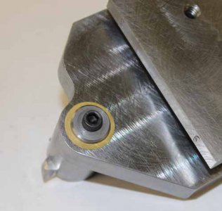
Looks great! One suggestion to consider (or maybe you have already dealt with this in a different way). On my little hemi-cutter, I inserted a brass shim washer & used Locktite blue on the bolt thread. This was cheapo way to set an appropriate amount of friction between the base & pivot post. It needs to slide/rotate, not sticky tight but also not loose. If the joint loosens up (in my case bolt loosened a bit) the tool can chatter. That might be amplified on your radius tool with the taller pillar & tougher material.

I'm still trying to get my head around the cutting motion. Do you set the plate up so the cutting is centered like green circle overlay? So to graduate cuts you just move the carriage X-axis from right to left like a regular ball cutter & cut from web tangent point to ~6-oclock position... then flip the plate to do the other side?
IMG_0625_edited-1.jpg

12-16-2016 0002.jpg
 
Looks great! One suggestion to consider (or maybe you have already dealt with this in a different way). On my little hemi-cutter, I inserted a brass shim washer & used Locktite blue on the bolt thread. This was cheapo way to set an appropriate amount of friction between the base & pivot post. It needs to slide/rotate, not sticky tight but also not loose. If the joint loosens up (in my case bolt loosened a bit) the tool can chatter. That might be amplified on your radius tool with the taller pillar & tougher material.

The pivot boss is polished steel riding in the compound rest centering pocket cast iron cross slide with a o.oo1" clearance fit. With a light coat of grease on the boss and under the base it is very smooth. The cap screws/t-nuts are set to where it will just turn easily. I was a little concerned about chatter and deflection with the tall post. It had no issues with the test cut. It may be different when I turn the larger piece. If there is an issue I will weld a gusset to the post and base to stiffen it up.

I'm still trying to get my head around the cutting motion. Do you set the plate up so the cutting is centered like green circle overlay? So to graduate cuts you just move the carriage X-axis from right to left like a regular ball cutter & cut from web tangent point to ~6-oclock position... then flip the plate to do the other side?

Correct.
 
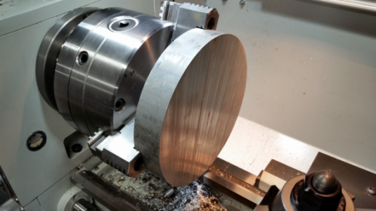
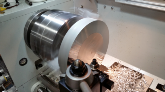
I picked up the material today but unfortunately it is short. I asked for a 1.6" length and they got me a 1.4" piece. The material is free from one of our sponsors so I didn't complain, we'll just alter the part to fit the stock.


HW01.png HW02.png

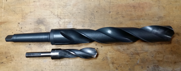
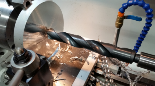
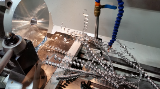
I finally got to use my 1.5" drill bit. :grin: The 1.5" next to a 1"
Drill01.png HW03.png HW04.png

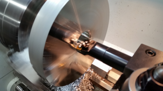
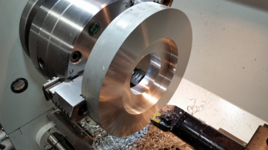
and then the 1-1/4" boring bar. Makes quick work of it.

HW05.png HW06.png
 
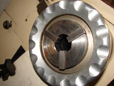
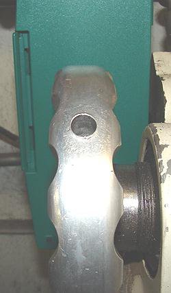
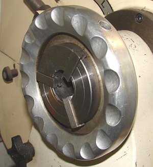
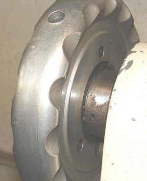
I think you want to work harder than what is required, it's a simple hand wheel. Here's one I made for an outboard scroll chuck. It's periphery is more like a handrail shape than a true radius.(trapezoidal) I used radius ed hss tools and a big file. The side cuts are angled.
chuckwheel1.jpg chuckwheel2.jpg chuckwheel3.jpg chuckwheel4.jpg
The finger grooves were put in with a 1" ball endmill.
 
Back
Top