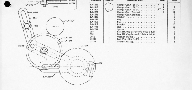
Rock, can you take a second picture of the "stop bracket"? In the illustration I posted and the parts diagram below there is a long slot in the Stop Bracket P/N LA-517.
To lift the gear into position, three (3) bolts need to be loose.
View attachment 482541
- Bolt 052 on the Stop Bracket
- Bolt 038 on the Change Gear Bracket (banjo)
- Nut LA-786 on the idler gear so the gear can slide on the Change Gear Bracket/banjo up into contact with the stud gear.
Sorry, I don't think we thought to mention needing to loosen the idler gear. The things we forget. Sorry. Maybe that is the rest of the problem.
Note the nut has a Logan part number because it isn't a standard nut to hold on the idler gear and any gear used as a spacer (a place to store the thing). When the stop bracket is pulled up
and the idler gear is slid on the Change Gear Bracket/banjo, the diagram below is pretty accurate on where the Stop Bracket will be. When the idler gear is in position, there should be a fair amount of the slot above the bolt head. If yours is solid, no slot, that is the problem. The wrong stop bracket is installed.
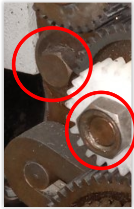
I've circled the
3 (three) bolts that need to be loose to slide the idler gear on the banjo into contact with the stud gear.
View attachment 482520
The Logan 8XX lathes have a different spindle gear (circled), that's why they have a 24 tooth "stud gear" vs. the 36 tooth used on the 9/19XX lathes. I learned the 19XX series also use a 36 tooth stud gear.
Sadly, the 9XX manual appears to have has an 8XX threading table in it! It shows no 36 tooth set-ups. Now that is something to research!!!
I wonder if that's why you appear to have that nylon 24 tooth gear??? Can you give us a picture of the threading/feed table on your QCGB?
View attachment 482523
The
wrong threading table from the 9XX manual.
View attachment 482524
Found on the internet (Lost Creek Machine, a good place of business IMHO) the correct 9/19XX thread/feed table with a 36 tooth stud gear. Rock, what table is on your QCGB?
View attachment 482545