-
Welcome back Guest! Did you know you can mentor other members here at H-M? If not, please check out our Relaunch of Hobby Machinist Mentoring Program!
You are using an out of date browser. It may not display this or other websites correctly.
You should upgrade or use an alternative browser.
You should upgrade or use an alternative browser.
Optimum MH 50V mods and accessories
- Thread starter Unlogic
- Start date
Thanks for the kind words, I'm trying to cut as few corners as possible but my build is still far from the level precision that Lukas Fässler has on his conversion (https://forum.zerspanungsbude.net/viewtopic.php?t=43263).
I haven't done any scraping only added some shims where necessary so far.
I haven't done any scraping only added some shims where necessary so far.
Yeah, Soldernerds work is really outstanding, but I'm missing the knowledge and time to do this on my machine.Thanks for the kind words, I'm trying to cut as few corners as possible but my build is still far from the level precision that Lukas Fässler has on his conversion (https://forum.zerspanungsbude.net/viewtopic.php?t=43263).
And you talk about scraping - I didn't even fix my column yet.... :-D but it is on my list: first the z-motor, then play in y-axis and then modify and install my new (old) boring head
I need to make hydraulic valves, so hopefully i will be finished soon with my mods...
It feels like I've been working on the mechanical part of the CNC conversion forever but I'm slowly getting closer to having all the parts finished.
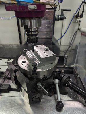
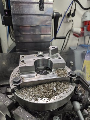
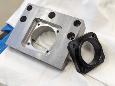
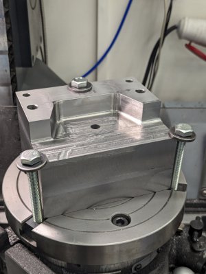
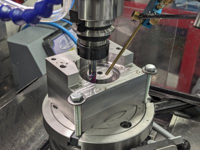
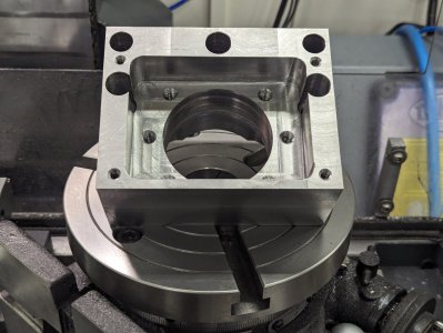
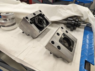
Milled the ball screw bearing block mounts for the X axis from two really solid pieces of steel. The machine mills steel surprisingly well however compared to aluminum the material removal rate is very slow and the tool life is much shorter.
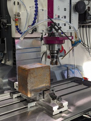
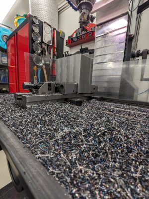
Just squaring up the stock when the pieces are this big take a fair amount of time. In order to speed up the process a bit I band sawed of the excess material.
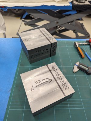
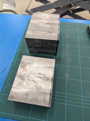
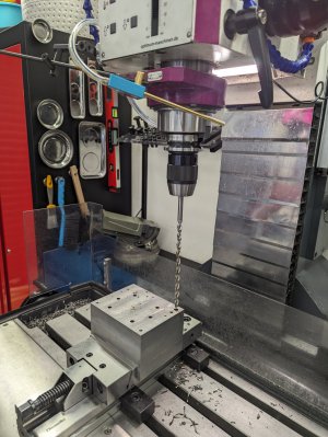
Here is the process of milling the features on the two blocks.
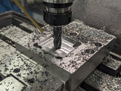
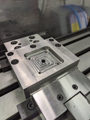
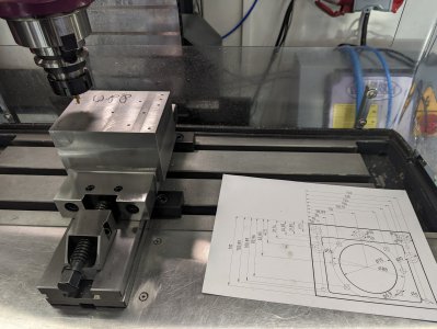
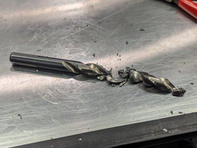
Had a close call when a drill shattered itself in one of the deep holes. Luckily I was able to pry out all the parts of it and continue drilling with a longer drill.
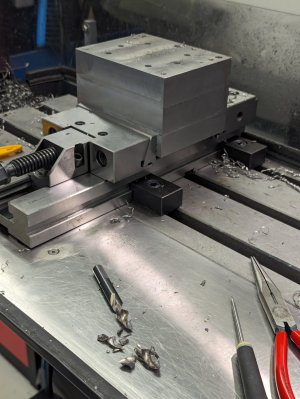
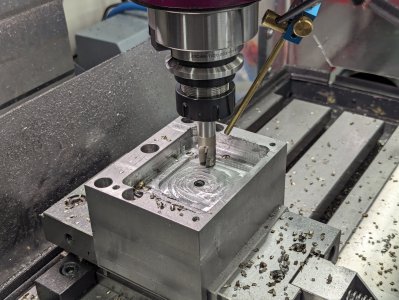
In order to make the holes in there larger pieces I used the rotary table. It took a while but worked surprisingly well in the end.
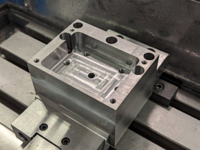
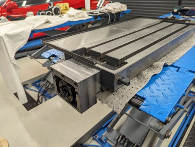
A quick test fit of one of the bearing block mounts on the table.
Milled the ball screw bearing block mounts for the X axis from two really solid pieces of steel. The machine mills steel surprisingly well however compared to aluminum the material removal rate is very slow and the tool life is much shorter.


Just squaring up the stock when the pieces are this big take a fair amount of time. In order to speed up the process a bit I band sawed of the excess material.


Here is the process of milling the features on the two blocks.


Had a close call when a drill shattered itself in one of the deep holes. Luckily I was able to pry out all the parts of it and continue drilling with a longer drill.


In order to make the holes in there larger pieces I used the rotary table. It took a while but worked surprisingly well in the end.


A quick test fit of one of the bearing block mounts on the table.

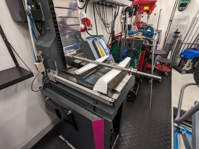
With the parts for the X-axis done it was time to focus on the Y-axis. I didn't have all the measurements for that axis so I had to take apart the machine in order to get them.
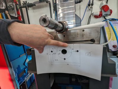
Took a few measurements and made a drawing in FreeCAD. After a few attempts I had a drawing matching the stock mounting holes.
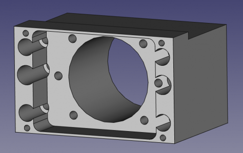
This is how the 3D model in FreeCAD looks for the Y-axis bearing block mount.
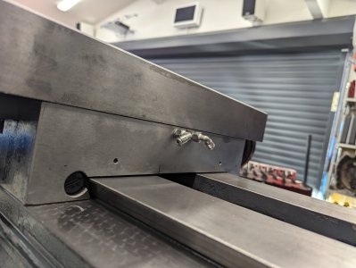
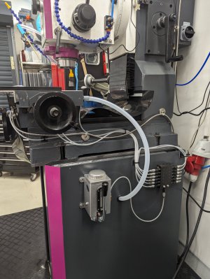
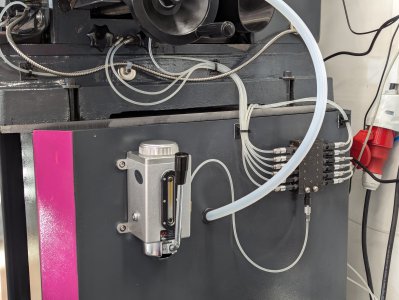
While I had the machine apart I decided to install the central lubrication stuff I've had laying around for almost two years. This took quite some time as I had to do the oil retaining grooves by hand using a Dremel...
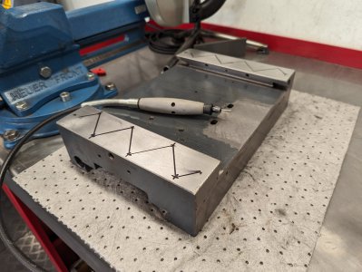
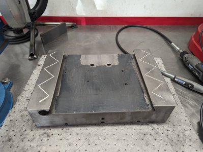
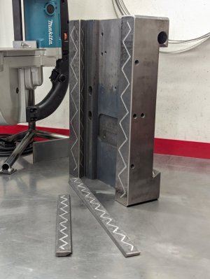
Next up was drilling the holes for the oil line connectors.
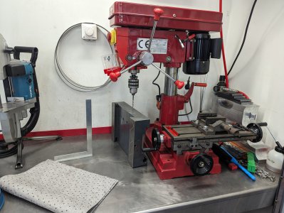
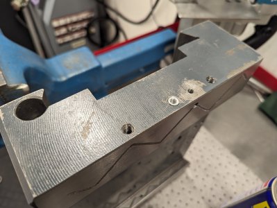
I also added for bolt holes for the Y-axis ball screw nut mount. I added these in advance so that I hopefully wont have to remove the saddle when the time comes to install the ball screw.
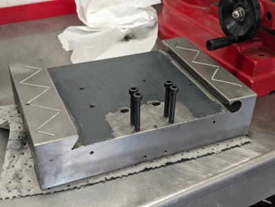
Then I started assembling the machine again and installing the connectors for the oil lines. I really like these stainless push in connectors, I bought them on AliExpress from this store: https://www.aliexpress.com/item/1005002771044559.html
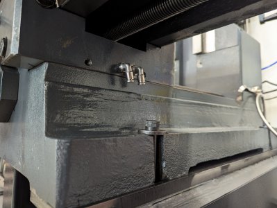
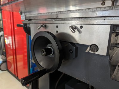
While I had everything apart I remembered that I needed to redo the drain for my flood cooling.
Previously I had the drain from the table go down to the top of the stand and then through a filter there and on to the tank at the bottom of the stand.
However after a little flooding accident when the filter on the drain from the top of the stand got clogged and coolant overflowed on to the shop floor I decided to change the setup to prevent that from happening again.
I now have a direct drain from the table down to the tank while at the same time retaining the drain from the top of the stand so that the oil which seeps out from the lubrication drain down into the tank too.
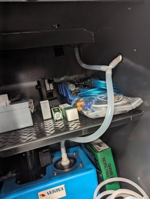
This is how it looks from the outside with all the hoses installed.

Took a few measurements and made a drawing in FreeCAD. After a few attempts I had a drawing matching the stock mounting holes.


This is how the 3D model in FreeCAD looks for the Y-axis bearing block mount.

While I had the machine apart I decided to install the central lubrication stuff I've had laying around for almost two years. This took quite some time as I had to do the oil retaining grooves by hand using a Dremel...


Next up was drilling the holes for the oil line connectors.


I also added for bolt holes for the Y-axis ball screw nut mount. I added these in advance so that I hopefully wont have to remove the saddle when the time comes to install the ball screw.

Then I started assembling the machine again and installing the connectors for the oil lines. I really like these stainless push in connectors, I bought them on AliExpress from this store: https://www.aliexpress.com/item/1005002771044559.html


While I had everything apart I remembered that I needed to redo the drain for my flood cooling.
Previously I had the drain from the table go down to the top of the stand and then through a filter there and on to the tank at the bottom of the stand.
However after a little flooding accident when the filter on the drain from the top of the stand got clogged and coolant overflowed on to the shop floor I decided to change the setup to prevent that from happening again.
I now have a direct drain from the table down to the tank while at the same time retaining the drain from the top of the stand so that the oil which seeps out from the lubrication drain down into the tank too.

This is how it looks from the outside with all the hoses installed.


It should be mentioned that apart from just adding groves for the oil I also stoned the gibs. They had a very rough surface for some reason which tended to cause binding. With just a quick stoning and the central lubrication I'm now able to tighten the gibs harder but still have smoother movement than before. So that modification is something I should have done long ago.
While milling steel using insert tooling I've heard a metal rattling sound. It's always been there but when milling steel with insert tooling it was more pronounced.
I thought it was something in the gearbox or the drive for the quill but then today I thought of something that I remember seeing in Lukas Fässlers thread. The bar used to release the tool when the quill handle is pushed upwards.
It was a bit fiddly to get it removed as the electrical connections on the spindle motor are in the way but here is how the bar looked when I removed it.
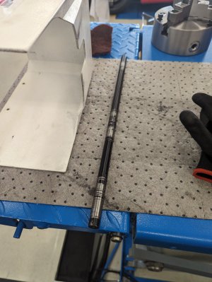
It's essentially a hardened steel rod which floats inside the quill and when doing rough cut's it vibrates around in there pretty good which can be seen on the wear marks.
Lukas Fässler made a whole new shaft but as I don't have a lathe I opted to add some heat shrink to the existing rod.
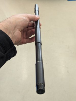
With the heat shrink in place it was much tighter fit to get the rod installed. In case it would get jammed I added a M6 thread to the top end of the rod.
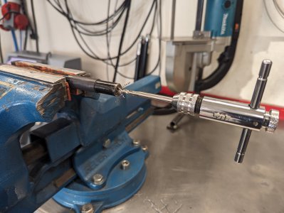
With the thread in place I can just bolt a large washer to the top of the rod and then pull down on the quill and the rod will automatically pull itself out.
The heat shrink on the steel bar made a huge difference, all the rattling is gone now which is very pleasant for the ears.
I'm not really sure if this construction is a common one or not but having a steel rod just floating around inside the quill seems a bit odd if you ask me... I'm probably going to revise the tool release mechanism later on.
While milling steel using insert tooling I've heard a metal rattling sound. It's always been there but when milling steel with insert tooling it was more pronounced.
I thought it was something in the gearbox or the drive for the quill but then today I thought of something that I remember seeing in Lukas Fässlers thread. The bar used to release the tool when the quill handle is pushed upwards.
It was a bit fiddly to get it removed as the electrical connections on the spindle motor are in the way but here is how the bar looked when I removed it.

It's essentially a hardened steel rod which floats inside the quill and when doing rough cut's it vibrates around in there pretty good which can be seen on the wear marks.
Lukas Fässler made a whole new shaft but as I don't have a lathe I opted to add some heat shrink to the existing rod.

With the heat shrink in place it was much tighter fit to get the rod installed. In case it would get jammed I added a M6 thread to the top end of the rod.

With the thread in place I can just bolt a large washer to the top of the rod and then pull down on the quill and the rod will automatically pull itself out.
The heat shrink on the steel bar made a huge difference, all the rattling is gone now which is very pleasant for the ears.
I'm not really sure if this construction is a common one or not but having a steel rod just floating around inside the quill seems a bit odd if you ask me... I'm probably going to revise the tool release mechanism later on.
Here is an update on the CNC conversion. There has been lots of progress since the last update so I'm going to have to divide it into multiple posts.
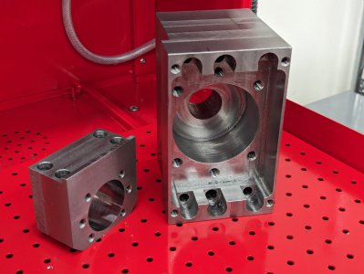
I milled the Y-axis bearing block and ball screw nut mount from the same type of steel that I used for the X-axis bearing blocks.
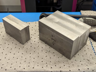
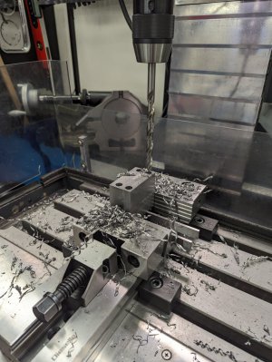
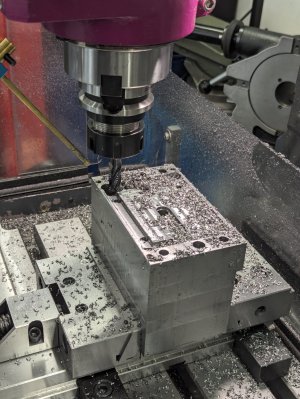
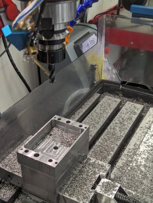
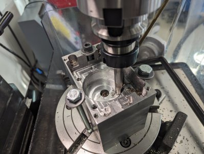
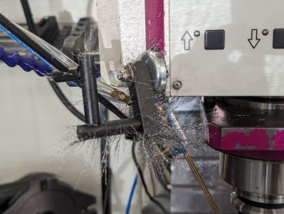
During the work above I learned why magnets should not be used on milling machines when milling steel...
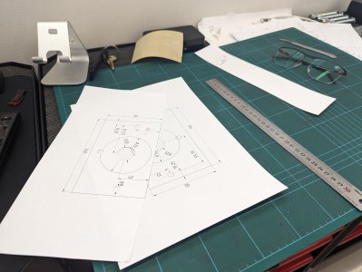
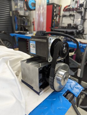
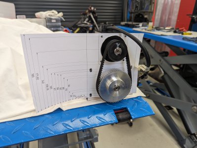
With all the bearing blocks milled I started work on the servo mounts. As usual I started with some rough measurements which I turned into FreeCAD models that I then printed on paper so they could be test fitted.
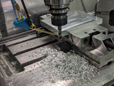
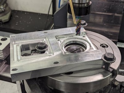
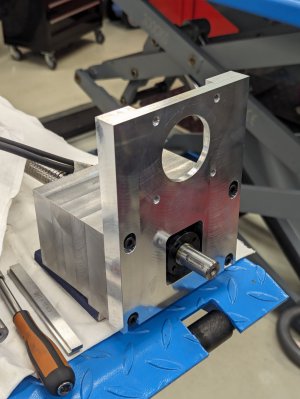
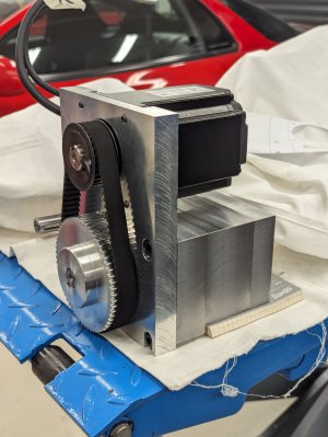
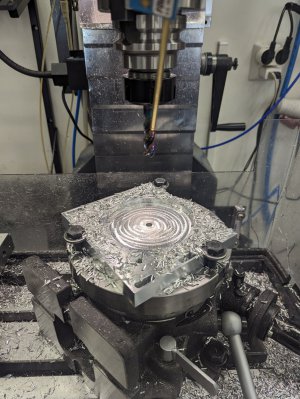
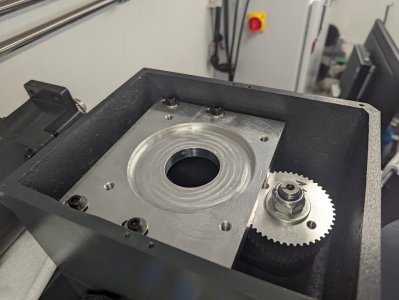
Here is the Y-axis servo mount being made from 6082 aluminum.
I milled the Y-axis bearing block and ball screw nut mount from the same type of steel that I used for the X-axis bearing blocks.


During the work above I learned why magnets should not be used on milling machines when milling steel...

With all the bearing blocks milled I started work on the servo mounts. As usual I started with some rough measurements which I turned into FreeCAD models that I then printed on paper so they could be test fitted.
Here is the Y-axis servo mount being made from 6082 aluminum.


I then moved on to the X-axis servo mount which I milled from the 7050 aluminum. The 7050 aluminum machines much more nicely than 6082 as it's a bit harder and less "gummy".
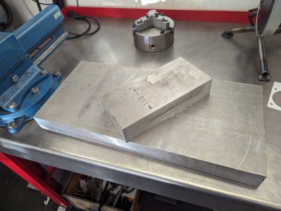
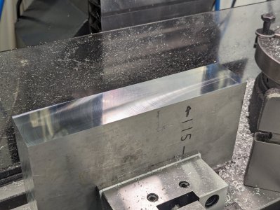
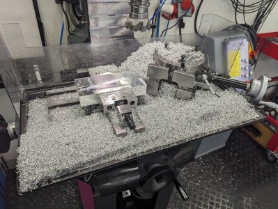
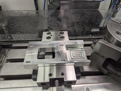
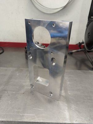
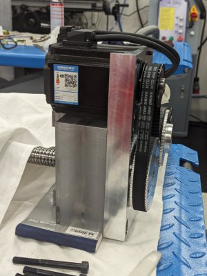
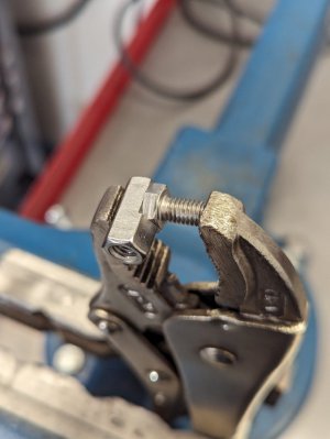
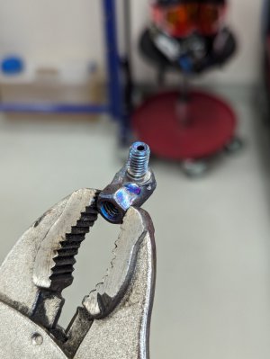
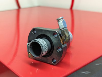
With the X-axis servo mount done I turned my attention to a small side project. I needed to relocate the quick connect fitting for the lubrication hose on the Y-axis ball screw as it would hit the casting of the machine otherwise.
I used a short stainless bolt and a long stainless nut to weld a small adapter.


Next up was the Z-axis servo mount and it was at this point with the last template that I realized that I didn't have to manually cut out my paper templates before test fitting them.
My wife has a Cameo cutting machine which could cut them for me. It would have saved me many hours if I had realized this at the beginning of the project
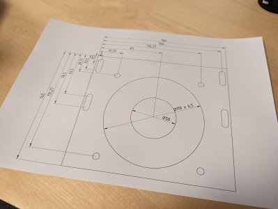
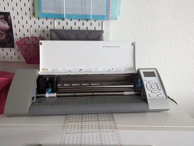
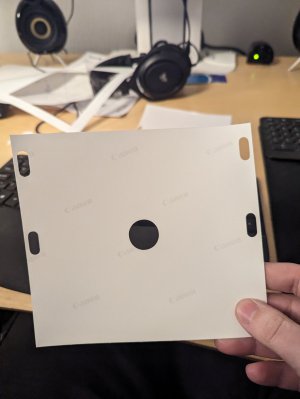
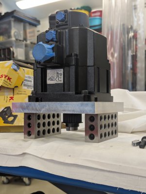
With the design verified using the paper template I milled the servo mount from 6082 aluminum.
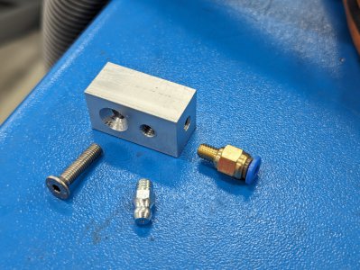
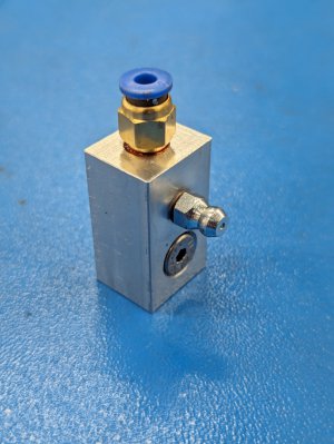
With the final servo mount done it was time for another side project. I need an adapter from grease nipple to quick connect hose so that I could lubricate the Y-axis ball screw nut.
My wife has a Cameo cutting machine which could cut them for me. It would have saved me many hours if I had realized this at the beginning of the project


With the design verified using the paper template I milled the servo mount from 6082 aluminum.


With the final servo mount done it was time for another side project. I need an adapter from grease nipple to quick connect hose so that I could lubricate the Y-axis ball screw nut.


