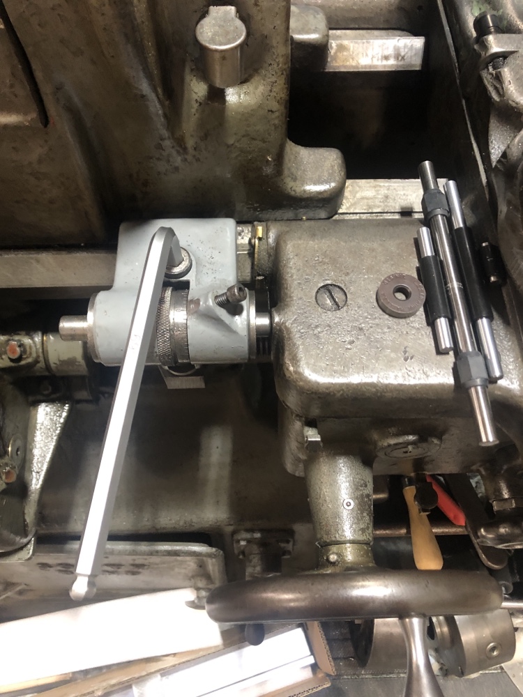
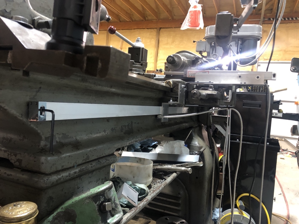
Yes, I got the bend wrong and it tilts up. But the reader is mounted straight and it only needs to be held in one spot. Ugly but I can live with it.
If it proves too weak, I can run a brace over to the taper attachment frame. But so far it seems sturdy enough.
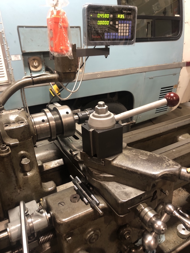
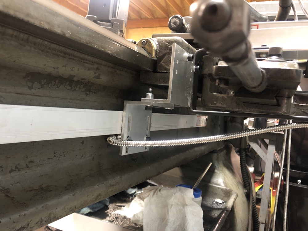
Yes, I could only get the good taps to go in about a half inch, but finishing with the bottoming tap was enough for the screws that came with the scales. A bigger problem was the holes wandered off square in that gooey steel.
I drilled these in my old press—230 RPM. That’s pretty slow for a drill that size, but that’s what that stuff needed. The 350 RPM slow speed of my better press was too fast. Bigger holes tolerated it better than smaller holes.
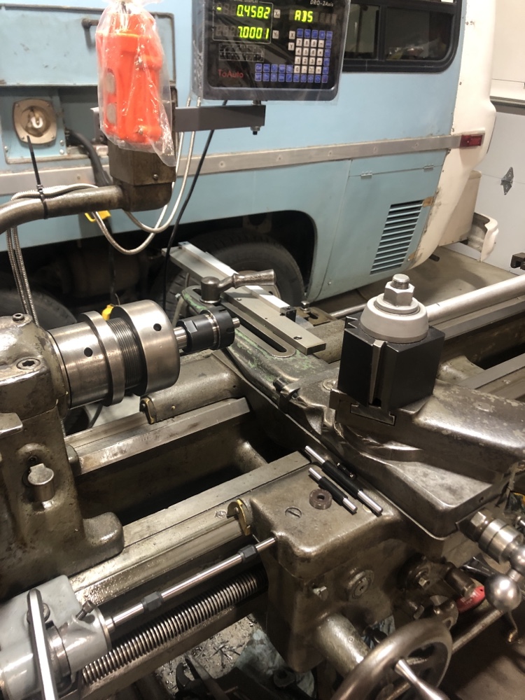
When I broke the tap, I had to set it aside for a week while I thought dark thoughts. I even bought an aluminum bar 1/2 x 1-1/2 to remake it. But the new drills in the same McMaster order worked better.
Rick “at least the bandsaw would cut it” Denney
If it proves too weak, I can run a brace over to the taper attachment frame. But so far it seems sturdy enough.
Yes, I could only get the good taps to go in about a half inch, but finishing with the bottoming tap was enough for the screws that came with the scales. A bigger problem was the holes wandered off square in that gooey steel.
I drilled these in my old press—230 RPM. That’s pretty slow for a drill that size, but that’s what that stuff needed. The 350 RPM slow speed of my better press was too fast. Bigger holes tolerated it better than smaller holes.
When I broke the tap, I had to set it aside for a week while I thought dark thoughts. I even bought an aluminum bar 1/2 x 1-1/2 to remake it. But the new drills in the same McMaster order worked better.
Rick “at least the bandsaw would cut it” Denney
")