PM1440-2SM VFD conversion

yarm2111

H-M Supporter - Silver Member
Joined
Oct 5, 2023
Messages
32
I'm at the planning stage of the VFD conversion for my 5 month old PM1440-2SM and would like to thank Mark @mksj for all his efforts. It is huge help for me.

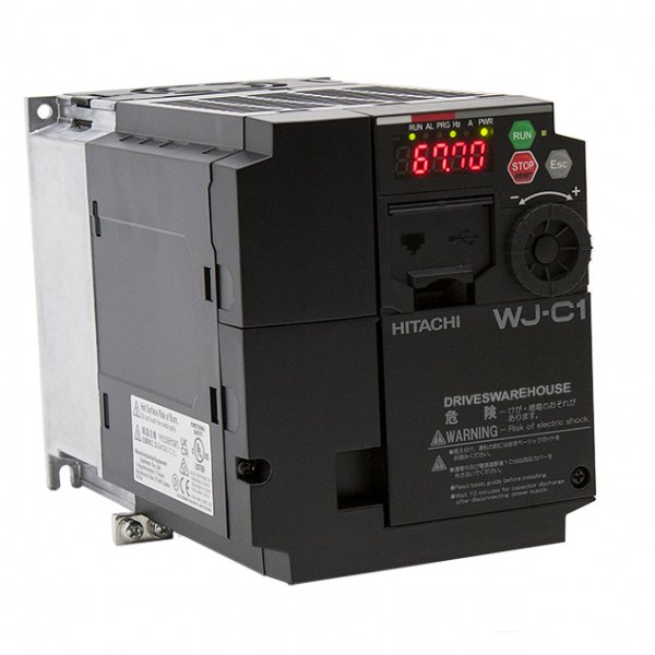
The good thing is that existing Forward and Reverse contactors have unused NO auxiliary contacts. It would allow me to keep all low voltage circuitry as is. I ordered Hitachi WJ200-022SF and Leeson 3HP motor.

The existing single phase motor appears to be a custom hybrid between metric IEC 90L and 100L. All mounting dimensions are as 90L, but shaft is 28mm as for 100L. And also shaft to mount dimension is 100mm, not 90mm as should be for 90 frame.

The new Leeson motor is 100L and significantly beefier than original, so mounting is going to be a challenge. I was not able to find 3HP, 4 pole motor in 90 frame. I think nobody makes them.

I drafted a preliminary schematic, used low voltage part from the PM manual, and shamelessly photoshoped WJ200 circuitry from one of Mark's many conversion schematics. Still, need to map connections on the terminal strip and create a wire list.

Would appreciate any comments and suggestions.
Thanks Mike
 

Attachments

  • PM-1440-2SM_schematic-2.pdf
    1.4 MB · Views: 48
It should work as outlined, input 4 (USP) can be directly wired to P24 (on all the time), it prevents the VFD from going into a run mode on power up. The E-Stop should have two NC switch blocks, one side is for the current 24VAC side and locks out the contactors and the other side locks out P24. I use 2-3 levels of redundancy in the rare chance that a switch/contact fails. Brake switch needs to be a dual pole NC/NO, one side for interrupting power to the contactors/power relay/contactor, the other side connects P24 to the free run command. Automation Direct has some less expensive versions then the SquareD, they come in different configurations and are well built.

You have two options on the jog, one is using the contactors for the direction with a JOG signal to the VFD, the other is direct connections to the respective VFD inputs, if 2 switch blocks it requires additional diodes. But as you have it indicated the contactors would lock out the run direction input in case of a fault.

When fitting a replacement 3 phase motor on many of these smaller lathes with the motor on the back, the motors are often a weird size and replacement motors are a challenge. I typically recommend switching to a US frame TENV motor which are very compact in size (E470A Marathon Severe Duty 3 hp 1800 RPM 230/460V 3-Phase 182T Frame TENV (rigid base) Motor). They may require either a different motor pulley or boring the current motor pulley, the shaft size is 1.125". The metric motors from Marathon, Leeson and Baldor are all very similar, they are good but the TENV in an inverter/vector style have a wider constant torque range and can handle a higher overload rating. Since you have multiple gear speed selection you do not need the wide motor range in a 2 or 3 speed gear head.

You should remove the high voltage motor wiring to the for/rev contactors, directly wire the motor to the VFD outputs.
Mark
 
@yarm2111

I realize you are well on track to do your conversion and that Mark is a big help in this. As Mark noted, you do not want any relays contacts between the motor and the VFD.

However, if for reference or additional knowledge, you want to see my approach for my PM1140GT you can get my write up at the posting shown below. Attachment Part 1 describes the factory original circuity for my 3phase system, while attachment Part 2 describes my conversion. Maybe they are some use to you, especially in how to hook up the VFD since I used the same Hitachi WJ200-022SF.

VFD conversion using solid state electronic components.

Also, @bdstark is in the process of doing a similar conversion now. He is also adding a new chuck Key interlock which is kind of a nice safety feature and provides a hanger so that you can find your Key(s). (i.e. don't run the lathe while the chuck key is still inserted!) He provides a link for his 3-D printed key hanger/interlock design.
The PCB from @B2 has been fantastic, and being able to bench test the functionality before attaching to a $900 VFD is comforting. The solid state design is pretty simple, certainly less expensive then the relays, while being more flexible with the limited space. Being able to iterate in design, without large wiring changes at the lathe/VFD is great and something that can't be easily replicated with relays, especially indoors at my desk. Relays are simple to reason about, and the solid state design takes extra mental effort, but the complexity is due to additional features that can be extended, something relays can't easily replicate.


Dave L.
 
You might also want to check out how @Jake P dealt with the motor mount challenges on his PM1440GT:

 
I noticed that your lathe version has two pulley settings, which you would not need if you do a VFD conversion. I would set the operating range of the motor to 20-90Hz which will give you the same top end speed as the VFD version of this lathe. I would use the original contactors, what you propose is the easiest and least expensive route, I see no reason to rip it all out. When removing the high voltage wiring to the Forward and Reverse contactors also remove the overload relay. This should be pretty similar to the basic VFD install I outlined/posted for the 1440GT. The parameters for the WJ200-022SF should also be similar to what has been posted, if you have any questions PM me and I can assist you if needed. I would add a simple tach. to give you the spindle RPM. I would suggest putting the speed pot where the power light is in the front panel and putting the power light in the E-Stop, but an alternative is to put the speed pot in the tachometer box as in the system build below, it may need to be a bit wider to accommodate it. I mount the tachometer display in the bottom of the box as shown for a cleaner look, and fabricate and adjustable L bracket that screws to the back.
DIGITEN 4 Digital Red LED Tachometer RPM Speed Meter + Hall Proximity Switch Magnet Sensor
20240327_123604.jpg


20240327_123831.jpg

20221231_161158.jpg
 
Thanks to everybody, very helpful! Mark, thanks for the tach link, good to know this one works. There are ton of them at Amazon with mixed reviews.
Yes, I'm going to remove all high voltage wiring (no overload relay), but don't want to disable my lathe just yet. Still waiting on the motor from ebay. Other parts are slowly coming in. WJ200 mounting is next. I would like to put it in the existing enclosure, sideways in front of the terminal board, hinged for access. Will see how it works with wiring harnesses attached. I ordered motor cable 12AWG shielded. Probably very rigid. If hinging did not work, I may relocate transformer and coolant relay and put WJ200 in "normal" way. We shall see.
Thanks Mike
 
Question - in order to program WJ200 with PC, do I need to apply 240VAC to it, or it will get power from USB?
 
You do not need to use shielded motor cable for such a short distance, also 3 phase 3hp motor is only around 8A which is 14AWG, which can be used for motors inclusive of 5Hp depending on the cable length. The WJ200 needs to be powered (240VAC on that model) to program it. Newer models either need an external 24VDC source or some use the USB cable power. The WJ200 series is being replaced with a newer model, but they both operate the same.
 
Hi @yarm2111 (Mike)

If you look at my write up you will see that one of the useful additions that I made was to add a small volt meter/display to the control panel. This is connected to the wiper of the pot that provides the control voltage to the VFD. Then I programed the maximum VFD (around 100Hz rather than 90) so that it occurred when the pot was set to yield about 10 volts. Hence when the volt meter read 10 volts it implied that the VFD was going to be outputting 100Hz. This provided an easy to digest scale conversion. The reasoning for doing this is that the VFD displayed Hz value does not turn on until you turn the motor on. Hence, you are in the dark as to how fast the motor is going to run at prior to turning it on if you cannot see the pot value going to the VFD.

While you will have the pot knob orientation to look at they are commonly not very accurate. Also the VFD response is not totally linear to the potentiometer setting. This means that neither the volt meter technique nor just observing the pot knob orientation is perfect but good enough to give you an idea of how fast (HZ) the VFD is set to. . So when programing the VFD I sat it up so that the volt meter reading was pretty accurate at when the frequency was set to be 60Hz rather than just at 100Hz. This is explained in my write up. I listed the voltmeter that I chose in my write up. See page 28 plus in the circuit diagrams. https://www.hobby-machinist.com/att...-vfddescript-links-dnl-l910_1440b-pdf.378083/

VFD conversion using solid state electronic components.


Anyway, since you seem to be planning to add the RPM meter you could easily add the volt meter. Another virtue of adding the RPM meter and the Volt meter you will not need the power on light on the front of your display. Anytime power is on the meters will be lighted. Also, I noted that the RPM meter that Mark suggested is sold by DIGITEN electronics. They are a seller on Aliexpress, as well as Amazon. However at their Aliexpress store you will find that they both sell things a little cheaper and you will find that they advertise a lot more items. Plus you can get other color displays if you so like. If you continue to read to the end of the thread for my install you will see that I added a counter to my system so that I could count the spindle revolutions and could resolve 1/10 of a revolution. It connects to the same Hall effect sensor that is used for the RPM meter. I got that counter from DIGITEN as well. https://www.hobby-machinist.com/thr...-components-pm1440gt-vfd-3-phase.95058/page-3

DIGITEN AliExpress is below. On this page you can see links to RMP, VOM, and Counter displays.


By the way, many of the RPM meters are designed to work in automobiles (12 volt systems). Hence they commonly have a maximum power supply voltage of 15 DC volts not the 24V DC or 24VAC that are normally used in lathe control systems. You will have to provide that. I used 24VDC for my electronics as the VFD is designed for this. However, I did not want to use the VFD internal supply as I was concerned that if it was over loaded burning it out would probably ruin the VFD. So I installed an separate 1 Amp 24Vdc supply. I then used an IC to provide 12volts for all of the displays. If I recall it is a simple three terminal LM7812. You just feed in the 24 volts one terminal, connect one terminal to ground, and the third terminal provides 12 Volts DC.

Dave L.
 
Dave thanks, you have very nice setup. My plan is to make basic system first, I can always add stuff later. For tach I ordered 12VDC Meanwell DIN rail power supply. The problem is that I don't have any existing rail exposed anywhere. ☺ Will add short piece somewhere in the box.
Mike
 
Back
Top